RAC6182 Industrial Computer for the Windows CE Operating System User Manual
Important User Information Solid state equipment has operational characteristics differing from those of electromechanical equipment. "Safety Guidelines for the Application, Installation, and Maintenance of Solid State Controls" (Publication SGI-1.1) describes some important differences between solid state equipment and hard-wired electromechanical devices.
Table of Contents Using this Manual Preface Who Should Use This Manual................................................... P-1 Purpose of this Manual .............................................................. P-1 Contents of this Manual............................................................. P-2 Manual Conventions.................................................................. P-3 Allen-Bradley Support...............................................................
toc-ii Table of Contents Adding/Removing Internal Components Chapter 4 Installing/Removing Front Bezel Assembly Items Chapter 5 Initial Operation and Setup Chapter 6 Chapter Objectives.....................................................................4-1 Safety Precautions......................................................................4-1 Thermal Considerations for Add-In Cards.................................4-2 Opening or Removing the Chassis.............................................
Table of Contents Display Settings toc-iii Chapter 9 Chapter Objectives .................................................................... 9-1 Setting Up the Display............................................................... 9-1 Touchscreen Calibration Chapter 10 Chapter Objectives .................................................................. 10-1 Setting Touchscreen Properties................................................ 10-1 Hardware Monitor Chapter 11 Chapter Objective ..............
toc-iv Table of Contents System Troubleshooting Chapter 15 Chapter Objectives...................................................................15-1 Hardware Diagnostics ..............................................................15-1 Troubleshooting Procedure ......................................................15-1 Troubleshooting Check Lists ..................................................15-2 Resetting the Windows CE Registry ........................................
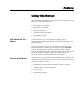
Preface Using this Manual Read this preface to familiarize yourself with the rest of the manual. The preface covers the following topics: • who should use this manual • the purpose of the manual • contents of the manual • conventions used in this manual • Allen-Bradley support Who Should Use This Manual Use this manual if you are responsible for installing, using, or troubleshooting the RAC6182 Industrial Computer for the Windows CE Operating System.
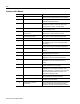
P-2 Contents of this Manual Chapter Title Contents Preface Describes the purpose, background, and scope of this manual. Also specifies the intended audience. 1 Computer Features Shows the different versions and features of the RAC6182 Industrial Computer. 2 Installation Describes how to install the RAC6182 Industrial Computer in a panel or enclosure. Also how to connect power, network, and relay output.
P-3 Chapter Title Contents Appendix A Specifications Provides physical, electrical, environmental, and functional specifications. Appendix B Processor Board Specifications Provides information on the RAC6182 Industrial Computer processor board. Appendix C RAC6182 Compatible Devices Lists the devices that are compatible with the RAC6182. Appendix D RAC6182 Point-to-Point Communications Describes how to connect the RAC6182 to various devices.
P-4 Publication 6182-UM001D-EN-P
Chapter 1 Computer Features Chapter Objectives This chapter provides an overview of the RAC6182 Industrial Computer for the Windows CE Operating System including: • available versions • software • additional catalog items RAC6182 Industrial Computer Versions The RAC6182 is available with a variety of options: • Display and operator input - 7.7-in. STN display with touchscreen or touchscreen/keypad combination - 12.1-in.
1–2 Computer Features RAC6182 Industrial Computer Packing List The RAC6182 Industrial Computer is delivered with the following items: • Computer with preinstalled Windows CE operating system • Mounting clips (4) • Power supply terminal block • Output relay terminal block • RAC6182 Applications and Accessories CD-ROM • Installation Guide (Publication 6182-IN001A-EN-P) • Microsoft Windows CE License Agreement (Part 41061-185-01(A) • Software manuals and media for optional bundled software applications.
Computer Features 1–3 New user applications can be field-installed on the RAC6182 Industrial Computer. Chapter 15, Managing User Applications, describes the various methods for installing software applications. The software vendor should also provide instructions for loading the application program.
1–4 Computer Features Windows CE Applications Some useful Windows CE utility programs are included on the RAC6182 Applications and Accessories CD-ROM. These utilities include network tools to verify Ethernet connections, a registry edit tool, and a scribble application to test the touchscreen. See each application’s online help for details on the program’s features.
Computer Features Features of the RAC6182 Industrial Computer 1–5 The following illustrations show the major features and controls of the display versions of the RAC6182 Industrial Computer. RAC6182 Computer – 7.7 in.
1–6 Computer Features RAC6182 Computer – 12.1 in. Version with Keypad RAC6182 Computer – 12.1 in.
Computer Features 1–7 RAC6182 Computer Common Chassis Publication 6182-UM001D-EN-P
1–8 Computer Features RAC6182 Industrial Computer Connectors WARNING: EXPLOSION HAZARD! Substitution of components may impair suitability for Class I, Div 2 hazardous locations.
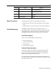
Computer Features LED Indicators 1–9 The following table shows the LED indicators on the RAC6182 Industrial Computer. Table A LED Indicators (Display Versions Only) Indicator Position Right Color Red Indicates Diagnostics. Indicates that one of the following conditions exists when lit: Overtemperature. Temperature inside the RAC6182 Industrial Computer enclosure is above defined threshold. Voltage. Voltages not within specification.
1–10 Computer Features Publication 6182-UM001D-EN-P
Chapter 2 Installation Chapter Objectives This chapter describes installation of the RAC6182 Industrial Computer for the Windows CE Operating System, including how to install the RAC6182 Industrial Computer in a panel using mounting clips. European Union Compliance The RAC6182 Industrial Computer meets the European Union Directive requirements when installed within the European Union or EEA regions and has the CE mark.
2–2 Installation The following replacement clips can be ordered from Rockwell Automation: Part Number Description 6189-2MTGKIT Mounting clips Quantity Package of 4 clips Use For Replacement item Tools Required In addition to the tools required to make the cutout, you will need a #2 Phillips-head screwdriver and a torque wrench. Mounting Clearances Allow adequate space for mounting, air flow, and maintenance.
Installation Mounting Dimensions 2–3 The following figures show the mounting dimensions for the RAC6182 Industrial Computer. Note: Measurements in these figures are expressed in millimeters [inches]. 7.7 in. Version with Keypad 12.1 in.
2–4 Installation 12.1 in.
Installation Mounting Cutouts 2–5 The following figure provides the dimensions for making the panel or enclosure cutout for the RAC6182 Industrial Computer. Table C Mounting Cutout Sizes Display Size Panel Mounting Height Width 7.7 in. version with keypad 197.8 [7.79] 295.8 [11.65] 12.1 in. version with touchscreen 256.8 [10.11] 337.6 [13.29] 12.1 in. version with keypad 256.8 [10.11] 389.9 [15.
2–6 Installation 4. Install the mounting clips. The mounting clips slide into the slots on the top and bottom of the RAC6182 Industrial Computer. 5. Gradually tighten the clips one at a time around the bezel using the specified sequence. Repeat this process at least three times until the clips are hand-tight and the gasket is compressed uniformly against the panel. 6. Tighten mounting clips to a torque of 10 in–lbs (1.1 N•m) in the sequence shown above. Do not over–tighten.
Installation Power Connections 2–7 A three-contact removable terminal block is used to connect power to the RAC6182 Industrial Computer. The RAC6182 Industrial Computer AC version accepts 120/240V AC. The AC power supply is autoranging. The DC version accepts 18-32V DC. The removable terminal blocks are different on the AC and DC versions and cannot be interchanged. ATTENTION: The power supply must be connected to an earth ground. Failure to follow this warning could result in severe electrical shock.
2–8 Installation A 3-part kit with the terminal blocks can be ordered from Rockwell Automation: Part Number 6189-2CONN Description 120/240VAC Unit terminal block (qty 1) 24VDC Unit terminal block (qty 1) Relay output terminal block (qty 1) Relay Output The RAC6182 Industrial Computer has a relay output. This output is a normally-open hard contact relay rated for 24VDC, 500mA. A twocontact removable terminal block is used to connect to the relay output.
Chapter 3 Connecting External Devices Chapter Objectives This chapter describes how to connect a variety of external devices to the RAC6182 Computer. This chapter’s topics include: • USB devices • PS/2 keyboard and mouse • Ethernet network connection (RJ45) • Serial devices • Parallel devices • External video monitors • Relay output Safety Precautions Make sure you disconnect all power to the RAC6182 Industrial Computer before performing any of the operations described in this chapter.
3–2 Connecting External Devices Connecting USB Devices The RAC6182 Computer has two USB ports. The Windows CE operating system currently only supports standard USB keyboard and mouse devices with its native device drivers. A vendor-specific Windows CE driver will be required for all other USB devices. The USB device can plug into either of the two side panel USB ports as shown below.
Connecting External Devices Connecting PS/2 Keyboard and Mouse 3–3 The mouse and keyboard plug into the side panel mouse and keyboard ports as shown below. Any standard PS/2 keyboard and mouse devices can be used. Both devices must be connected before power-up to be recognized by the Windows CE operating system.
3–4 Connecting External Devices Connecting to an Ethernet Network The RAC6182 Industrial Computer accommodates CAT5 twisted pair Ethernet cabling with RJ45 connectors to support 10 Mbps and 100 Mbps network data transfer rates. Shielded cabling is required to maintain EMI compliance. A ferrite collar is included with the RAC6182 and is intended for use with an Ethernet cable connected to a RAC6182. Install the collar for suppression of electromagnetic emissions and interference.
Connecting External Devices 3–5 Important: Performance degradation of your Ethernet communications is likely to result if the unit or cables are subjected to extreme radiated or conducted high-frequency noise. It is the user’s responsibility to properly route cables and condition input power in order to improve communication reliability. Proper cable routing and power conditioning is required to ensure reliable Ethernet communications in industrial environments.
3–6 Connecting External Devices Connecting Serial Devices The RAC6182 Computer has two serial ports – COM1 and COM2, both with DB9 male connectors. The COM1 port supports RS232, RS422, and RS485 physical signals. The COM1 physical signals are software-selectable. The COM2 port supports only RS232 physical signals. The COM2 port is used to connect to a host PC using ActiveSync. Note: You must use a null modem cable (6189-2NMCBL) to connect the COM2 port to a host PC.
Connecting External Devices Connecting Parallel Devices 3–7 The RAC6182 Computer has an ECP/EPP compatible parallel printer port with a DB25 female connector. This port can be connected to a parallel printer. The RAC6182 Windows CE operating system provides a PCL3 printer driver. If other printers are to be used, you must provide the associated Windows CE printer driver if available.
3–8 Connecting External Devices Connecting an External Video Monitor The RAC6182 Computer has an external HD15 video connector. It can drive an external monitor with VGA, SVGA or XGA analog video signals. Note: For information on setting the video resolution and refresh rate for an external monitor, refer to Chapter 10, Display Settings.
Connecting External Devices Connecting to Relay Output 3–9 The RAC6182 Industrial Computer has a relay output. This output is a normally-open hard contact relay rated for 24VDC, 500mA. A twocontact removable terminal block is used to connect to the relay output. Note: For instructions on connecting the relay output, refer to Page 2-8. The relay output can be used to drive a variety of peripheral signaling devices such as a tower annunciator light or an audible alarm or buzzer.
3–10 Connecting External Devices Publication 6182-UM001D-EN-P
Chapter 4 Adding/Removing Internal Components Chapter Objectives This chapter describes how to open the chassis of the RAC6182 Industrial Computer and remove or install: • PC add-in cards (PCMCIA) • PCI add-in card • RAM • DiskOnChip flash ROM Safety Precautions The RAC6182 Industrial Computer contains line voltages. Make sure you disconnect all power to the RAC6182 Industrial Computer before removing covers or access screws.
4–2 Adding/Removing Internal Components Thermal Considerations for Add-In Cards The RAC6182 Industrial Computer accommodates one PCI compatible add-in card. Due to thermal considerations with the unit, total add-in power is limited to 7W of power dissipation (within the product enclosure). Table J PCI Card Current Limits Opening or Removing the Chassis Voltage Current Limit at Specified Voltage 5V 1.0A 3.3V 0.1A 12V 0.1A -12V -0.
Adding/Removing Internal Components 4–3 To remove the chassis (display versions): 1. To remove the chassis completely from the front bezel, carefully disconnect the internal cables from the chassis printed circuit board. 2. Remove the set-screw in the hinge, and lift the back chassis off the front bezel hinges. To replace the chassis (display version): 1. To replace the chassis, remount the chassis onto the front bezel hinges and reinstall the hinge set-screw.
4–4 Adding/Removing Internal Components To open the chassis (non-display versions): 1. Disconnect power from the RAC6182 Industrial Computer. 2. Remove the 4 nuts securing the chassis to the front plate. 3. To close the chassis, reinstall the 4 nuts to secure the chassis to the front plate. Tighten the nuts to 6 - 8 in–lbs (0.7 - 0.9 N•m). Adding/Removing PC Cards (PCMCIA) One Type III PC card or two Type II PC cards (PCMCIA) may be installed in the RAC6182 computer.
Adding/Removing Internal Components 4–5 To install a PC card: 1. Locate the PC card slots on the side of the RAC6182. 2. Loosen the screw on the PC card retainer bracket covering the PC card slot, if necessary. 3. Insert the PC card into the desired slot. Make sure the PC card is fully seated and the slot ejector is out. Up to 2 Type II cards can be installed in the RAC6182. Note: Most PC cards are hot-swappable on the RAC6182. You do not need to turn off power to the unit.
4–6 Adding/Removing Internal Components Adding/Removing a PCI Card One PCI card can be installed in the RAC6182 computer. While the RAC6182 expansion slot is electrically compatible with any standard half-length PCI card, special Windows CE drivers are required to make a PCI card function on the RAC6182 computer. Refer to the application program to make sure it supports the desired PCI card.
Adding/Removing Internal Components 4–7 4. Hold the card by the edges and firmly press the card into the PCI connector. 5. Align the notch in the board retainer with the threaded hole on the chassis and install the screw. Hold the notch tightly against the screw before tightening. Tighten the screw to a torque of 6 - 8 in–lbs (0.7 - 0.9 N•m). 6. Check any connectors on the PCI card to make sure they are centered in the chassis opening. 7. Reinstall the screws to secure the top cover to the chassis.
4–8 Adding/Removing Internal Components 5. Hold the board at each end and carefully rock the board back and forth until the edge connectors pull free. 6. Store the board in an anti-static wrapper. 7. Install and secure a slot cover over the open slot. Tighten the screw to a torque of 6 - 8 in–lbs (0.7 - 0.9 N•m). 8. Reinstall the screws to secure the top cover to the chassis. Tighten the screws to a torque of 6 - 8 in–lbs (0.7 - 0.9 N•m).
Adding/Removing Internal Components 4–9 4. To remove the memory module, release the socket latches and carefully pull the module out of the socket. 5. Store the memory module in an anti-static wrapper. 6. To install the memory module, carefully push the module into the socket. Make sure the socket latches are engaged. 7. Reinstall the screws to secure the top cover to the chassis. Tighten the screws to a torque of 6 - 8 in–lbs (0.7 - 0.9 N•m).
4–10 Adding/Removing Internal Components ATTENTION: The DOC memory is sensitive to ESD and requires careful handling. Hold the DOC by the package – do not touch the pins. After removing the DOC, place the device in an anti-static wrapper. To access the DiskOnChip socket: 1. Disconnect power to the RAC6182. 2. Follow the procedures beginning on Page 4-2 to open the chassis. 3. Locate the DOC socket on the processor board, as shown on the diagram below. 4.
Adding/Removing Internal Components 4–11 5. Remove the DOC from its socket. Pull the device straight up. Be careful not to bend or damage the DOC pins. ATTENTION: Make sure to hook only the DOC with the extraction tool, and not the socket located directly below the DOC. Do not pull the socket from the printed circuit board assembly. Irreparable damage will result. 6. Store the DOC memory in an anti-static wrapper. 7.
4–12 Adding/Removing Internal Components Publication 6182-UM001D-EN-P
Chapter 5 Installing/Removing Front Bezel Assembly Items Chapter Objectives This chapter describes how to replace items in the RAC6182 front bezel assembly. The RAC6182 front bezel assembly consists of a plastic bezel with overlay (keypad and/or touchscreen), and a metal frame assembly that holds the LCD panel and associated interconnection circuit boards. The LCD panel has field-replaceable backlight tubes (12.1-in. versions only). The keypad bezel versions have removable function key legend strips.
5–2 Installing/Removing Front Bezel Assembly Items Disassembling the Front Bezel At times when repairing or replacing items on the front bezel assembly, you may need to disassemble the front bezel. You must disassemble the front bezel when you: • Replace the front bezel plastic overlay • Replace the vertical legend strips To prepare the front bezel for disassembly (all models): 1. Remove the RAC6182 from the panel or enclosure. 2. Follow the procedures on Page 4-2 to remove the computer chassis. 3.
Installing/Removing Front Bezel Assembly Items 5–3 To disassemble the front bezel (12.1 in. display with keypad): 1. Disconnect the keypad cable, touchscreen cable, backlight tube connectors, and the backlight power supply cable as indicated in the following figure: 2. Remove the 6 screws securing the metal cover to the frame. 3. If you are replacing the plastic bezel overlay or vertical legend strips, remove the 10 screws securing the metal frame and lift the metal frame away from the plastic bezel. 4.
5–4 Installing/Removing Front Bezel Assembly Items 7. Reinstall the 6 screws to attach the metal cover to the frame. Tighten the screws to a torque of 6 - 8 in–lbs (0.7 - 0.9 N•m). 8. Follow the procedures on Page 4-2 to reassemble the front bezel assembly to the computer chassis. To disassemble the front bezel (12.1 in. display with touchscreen): 1. Disconnect the backlight tube connectors as indicated in the following figure: 2. Remove the 6 screws securing the metal cover to the frame.
Installing/Removing Front Bezel Assembly Items 5–5 8. Reconnect the backlight tube connectors and backlight power supply cable. 9. Reinstall the 6 screws to attach the metal cover to the metal frame. Tighten the screws to a torque of 6 - 8 in–lbs (0.7 - 0.9 N•m). 10. Follow the procedures on Page 4-2 to reassemble the front bezel assembly to the computer chassis. Replacing the Front Bezel Plastic Overlay The plastic overlay on the RAC6182 Industrial Computer is field replaceable.
5–6 Installing/Removing Front Bezel Assembly Items 6. Follow the procedures in this chapter to reassemble the front bezel, routing and connecting cables as required. 7. Remove outside display window protective film and reinstall RAC6182 computer into panel or enclosure. The following are catalog numbers for the RAC6182 front bezel overlay assemblies. These assemblies include the plastic bezel, overlay, and legend strips only.
Installing/Removing Front Bezel Assembly Items Part Number Description 6189-2KEYKIT8 7.7 in. bezel legend strip kit (3 pcs) 6189-2KEYKIT12 12.1 in. bezel legend strip kit (3 pcs) 5–7 To replace the horizontal legend strip (7.7 in. & 12.1 in. versions): 1. Locate the exposed legend strip tab on the lower left side of the RAC6182 unit. 2. Carefully pull on the tab to remove the installed legend strip. 3.
5–8 Installing/Removing Front Bezel Assembly Items To replace the vertical legend strips (7.7 in. & 12.1 in. versions): 1. Follow the procedures in this chapter to disassemble the front bezel. 2. Place the front bezel plastic overlay facedown on a flat surface. Take care not to scratch the front overlay or display window. Locate the two exposed legend strip tabs as shown. 3. To remove the legend strips, carefully pull on the exposed tab. 4.
Chapter 6 Initial Operation and Setup Chapter Objectives This chapter provides information on: • operating recommendations • boot-up sequence • system reset Operating Recommendations Rockwell Automation recommends that you not operate the RAC6182 Industrial Computer with covers removed. An electrical shock hazard exists. In addition, removing the covers disrupts air flow and may result in overheating. All covers are required to maintain EMI compliance.
6–2 Initial Operation and Setup Note: The entire power-up process takes approximately 20 seconds. The display is not active for a large portion of the boot time, but the front panel LEDs toggle to indicate that the RAC6182 Industrial Computer is powering up. 4. Use the procedures in Chapter 15, Managing User Applications, to load and manage additional software applications and data files. 5. If your system does not boot up, or if you notice other problems, refer to Chapter 16, System Troubleshooting.
Chapter 7 Windows CE Operating System Chapter Objectives This chapter provides information on: • Windows CE architecture • Windows CE programs • Using Windows CE • Control Panel applications • RAC6182 Computer memory usage Windows CE Architecture The Windows CE operating system from Microsoft is designed to provide a portable, scalable, real-time operating system for embedded devices.
7–2 Windows CE Operating System Microsoft created hardware reference models for the Handheld (HPC) and the Pocket (PPC) PC so that third-party applications can run on these standard platforms. There are no hardware standards for embedded devices. The RAC6182 Industrial Computer is largely compatible with HPC and PPC, so applications that are compiled for the MIPS or MIPSFP may run on the RAC6182.
Windows CE Operating System 7–3 discusses how to use Microsoft ActiveSync to install and remove application programs on the RAC6182 Industrial Computer. Each application program must be compiled for the MIPS RISC processor. If the application program literature does not specifically identify the RAC6182 Industrial Computer as a compatible hardware platform, take caution if trying to install and run it on the RAC6182 platform.
7–4 Windows CE Operating System The taskbar across the bottom of the screen contains buttons for programs already running, along with a status area and a Desktop icon. You can alternately minimize and maximize an open application by clicking on its taskbar button. Double-clicking on any icon in the status area shows more information about that function. A single-click on the Show Desktop button (far right side of taskbar) minimizes all open windows and displays the RAC6182 Industrial Computer Desktop.
Windows CE Operating System 7–5 There is no Minimize button on the Windows CE command bar. Click the taskbar button to minimize a program window, or use the Show Desktop button to minimize all open program windows. Finding Files Select Start-Programs-Windows Explorer to locate files on the RAC6182 Industrial Computer. You can alternately double-click the My Computer icon on the Desktop to open the Windows Explorer program.
7–6 Windows CE Operating System Configuring the RAC6182 Industrial Computer There are several user-configurable settings on the RAC6182 Industrial Computer. These settings are accessed from the Windows CE Control Panel. Select Start-Settings-Control Panel to open the Control Panel window. Control Panel Applications The Windows CE operating system contains a number of native functions and interfaces. Many of these features are very similar to other Microsoft Windows operating systems.
Windows CE Operating System RAC6182 Memory Usage 7–7 The RAC6182 Industrial Computer has five internal memory areas.
7–8 Windows CE Operating System RAM-based storage memory segment is not persistent as in HPC devices, so all files stored here must be re-created at every startup. The program memory segment provides traditional computer RAM-like functions for holding application code, heaps, stacks, and data at runtime. The RAC6182 Industrial Computer loads the Windows CE operating system and any auto-start applications from the DOC flash ROM into the program memory at power-up.
Chapter 8 Keypad Operation Chapter Objectives This chapter describes how to configure and operate the front bezel keypad on associated RAC6182 versions. This chapter’s topics include: • Keypad operation • Keypad layout • Configuring the Keypad application Keypad Operation The 7.7 in. and 12.1 in. display versions of the RAC6182 Industrial Computer are available with a front bezel keypad. This keypad provides an operator interface to the RAC6182 Industrial Computer.
8–2 Keypad Operation Numeric Keypad The numeric keypad contains the following keys. The numeric keypad keys are blue. The NUMLOCK key changes the key definitions as shown below. The NUMLOCK status LED is lit when the NUMLOCK function is activated. Table M Numeric Keypad Functions Publication 6182-UM001D-EN-P Key 0 1 2 NUMLOCK On 0 1 2 NUMLOCK Off INS (insert) END (end) 3 4 3 4 PG DN (page down) 5 6 5 6 (none) 7 8 7 8 HOME (home) 9 . 9 .
Keypad Operation 8–3 Control & Navigation Keys The control and navigation keys are black. They have the following key definitions.
8–4 Keypad Operation Function Keys The function keys are located below and on either side of the display window. The 7.7 in. version has 11 function keys below the display (F1-F11), and a row of 8 function keys on each side of the display (K1-K8, K9-K16), for a total of 27 function keys. The 12.1 in. version has 14 function keys below the display (F1-F14), and a row of 10 function keys on each side of the display (K1-K10, K11K20), for a total of 34 function keys.
Keypad Operation 8–5 Table P Function Key (K-Key) Keypad Functions 7.7 in. Key K1 K2 K3 K4 K5 K6 K7 K8 K9 K10 K11 K12 K13 K14 K15 K16 Default right Alt + F1 right Alt + F2 right Alt + F3 right Alt + F4 right Alt + F5 right Alt + F6 right Alt + F7 right Alt + F8 right Alt + F9 right Alt + F10 right Alt + F11 right Alt + F12 right Shift + F1 right Shift + F2 right Shift + F3 right Shift + F4 12.1 in.
8–6 Keypad Operation Keypad Configuration Utility is required to program the function keys for different modes and characters. Multi-Key Lockout Mode Multi-key lockout mode disables any subsequent key presses while an existing function key is still depressed. When enabled and a function key is pressed, all other key presses are ignored until the function key is released. Likewise, if the Alt, Ctrl, or Shift keys are pressed, all function keys are inhibited until the modifier key is released.
Keypad Operation Setting Up the Keypad 8–7 You configure the RAC6182 Industrial Computer keypad using the Keypad application in the Windows CE Control Panel. To change the keypad operation: 1. To start the Keypad application, select Start-Settings-Control Panel. Select or double-click on the Keypad icon. 2. On the Repeat tab, select the following options as necessary: To enable repeating for all keys, select the Enable Character Repeat checkbox.
8–8 Keypad Operation 3. On the Multi-Key/Hold-Off tab, select the following options as necessary: To enable hold-off for all programmable (blue) keys, select the Hold-Off Mode checkbox. To adjust how much time must elapse before another programmable key is recognized, drag the Hold-Off Delay slider control. To enable multi-key lockout for all programmable (blue) keys, select the Multi-Key Lockout Enable checkbox.
Keypad Operation 8–9 The resultant codes for single key are often referred to as the definition or mapping of the key. The collection of all keys’ definitions is commonly called the Keypad Configuration. Hint: If you modify the Keypad Configuration, you should save the new configuration to a Keypad Configuration File (*.KY2). This file can be downloaded into other RAC6182 computers to provide the same keypad behavior, or used to reload the desired configuration into a replacement RAC6182 computer.
8–10 Keypad Operation 5. Select and open the file named “setup.exe”. 6. Follow the install instructions on the screen. To install the RAC6182 Keypad Configuration Utility software using Run: 1. Insert the CD named RAC6182 Applications and Accessories into your CD drive. 2. Click the Start button and select Run from the menu. 3. Browse the CD to the folder “Keypad Configuration Utility”. 4. Select and open the file named “setup.exe”. 5. Follow the install instructions on the screen.
Keypad Operation 8–11 Connecting the RAC6182 Computer to the PC Computer When the RAC6182 Keypad configuration Utility runs, it first looks for an ActiveSync connection to a RAC6182 computer. That is why essential first steps are to ensure that ActiveSync is installed on the PC and to establish an ActiveSync connection between the PC and the RAC6182 Industrial Computer. The connection can be serial or Ethernet.
8–12 Keypad Operation The window that contains the keypad configuration stored on the RAC6182 computer is named RAC6182 Keypad Configuration. Figure 1 7.7 in. Bezel with Keypad Figure 2 12.
Keypad Operation 8–13 You can now: • Modify the keypad configuration and download it to the RAC6182. • Modify the keypad configuration and save it as a *.KY2 file. • Recall and modify an existing keypad configuration (*.KY2 file) and download it to the RAC6182. Operations available from the menu bar are as follow: Select commands on this menu: To File Menu Open, close, and save configuration files, print preview and print keypad configuration files.
8–14 Keypad Operation Entering a Keypad Description The text edit box appears near the center of the keypad configuration window and allows you to enter a description to identify the Keypad Configuration. The text edit box accepts up to 128 characters. To edit a description, simply click in the text edit box and start typing or editing the text. With the cursor in the text edit box, click the right mouse button to open the popup menu.
Keypad Operation 8–15 Selecting Keys The table below shows how to select keys on the keypad. You must select a key before you can enable or disable the key or modify its configuration. To Select: Do This: The result is: Single key Click the left mouse button on the key. The selected key is highlighted with handles. Group of keys Click the left mouse button and drag the selection rectangle around the keys you want to select. The selected keys are highlighted with handles.
8–16 Keypad Operation keys enabled and others disabled, choosing the Enable Key command will enable all the selected keys. Opening a Saved Keypad Configuration To open an existing keypad configuration file: 1. Choose Open from the File menu or click on the tool bar. Figure 4 Open File 2. The dialog shows all keypad configuration files (*.KY2) in the “Look In:” folder. 3. Double-click the *.KY2 file you want to open or click on a *.KY2 file and then click the Open button.
Keypad Operation 8–17 Set the Default Configuration for Programmable Keys 1. Select one or more programmable keys or use the edit menu Select All Programmable Keys. See “Selecting Keys” above. 2. Choose Set Default Configuration from the Edit menu. Figure 5 Set Programmable Key Default The selected programmable keys are set to their default assignments. The default key assignments are listed at the end of this chapter.
8–18 Keypad Operation Set the Default Configuration for Any Key 1. Select one or more keys or use the edit menu Select All Keys. See “Selecting Keys” above. 2. Choose Set Default Configuration from the Edit menu. Figure 6 Set Key Default The selected keys are set to their default assignments. Nonprogrammable keys are enabled by default. The default key assignments are listed at the end of this chapter.
Keypad Operation 8–19 Editing the Programmable Keys To edit the definition of a programmable key: 1. Select a single programmable key. 2. Choose Key Configuration from the Edit menu or click the right mouse button on the key and choose Key Configuration from the popup menu as shown below. 3. Use the Edit Programmable Key dialog to view the current definition and establish a new definition for the programmable key. 4. Click OK or press Enter to save the definition and close the dialog. 5.
8–20 Keypad Operation The Edit Programmable Key dialog lets you modify the definition of the selected programmable key. The definitions are downloaded and stored in the registry of the RAC6182. Modifying a programmable key is not recommended unless required by the application software. Figure 8 Select and Edit Programmable Key When the Edit Programmable Key dialog box opens, it shows the current definition of the selected programmable key.
Keypad Operation 8–21 Text Edit Box The text box at the top of the dialog displays the current definition for a selected programmable key. You can enter a new definition directly into the edit box if the characters are printable (e.g., alphanumeric characters). You must enter nonprintable characters from the Add New Code list. While in the text edit box, use Backspace to remove existing characters and correct typing errors.
8–22 Keypad Operation Select Mode Determines how the contents of the Text Edit Box will be handled by the RAC6182 when the selected key is pressed. There are 3 modes, established by radio buttons. 1. In Macro/String mode, the key is defined as non-repeating and all key codes are sent as a single string when the key is first pressed. A key defined as a Macro/String can submit a sequence of up to 31 key presses to the application that is currently in focus.
Keypad Operation 8–23 2. In Make/Break Typematic mode, the key is defined as repeatable at the Repeat Rate established by the Keypad Properties Tool in RAC6182 Control Panel. The key “Make” codes are sent when the key is first pressed and the “Break” codes are sent when the key is released. If the key is held down, the “Make” codes repeat at the Repeat Rate.
8–24 Keypad Operation 3. In Run Program mode, the key is defined as non-repeating, and all key codes are sent as a single string when the key is first pressed. A key defined as a Run Program can submit a sequence of up to 80 characters. Unlike the other modes, wherein actions are directed at the application with current focus, this action is directed at the operating system to run the program that is named in the Text Edit Box. In the following example, the key press launches a program named “ProgramName.
Keypad Operation 8–25 Add New Code The Add New Code grouping on the dialog is a list of valid keys and modifiers that can be assigned to a programmable key. A modifier (Shift, Ctrl, Alt, Win or Win Appl) are enabled for a key code, by selecting the appropriate check boxes. These check boxes are dynamically updated so that only valid combinations are allowed. After selecting a key code and modifiers, click the Enter button to display the new code in the Text Edit box.
8–26 Keypad Operation Examples of Editing Key Definitions Example #1: Configure the K1 key as < (L)Win+e > which runs Windows Explorer: 1. Select the key labeled K1. 2. Choose Key Configuration from the Edit menu, or click the right mouse button on the key and choose Key Configuration from the popup menu. 3. In the text box, backspace to delete the current definition. 4. Under Select Mode, select Make/Break Typematic. 5. Select ’e’ from the Add New Code list. 6. Under Left, check Win check box. 7.
Keypad Operation 8–27 Example #2: Configure the K10 key perform a DIR /a /o /s command 1. Select the key labeled K10. 2. Choose Key Configuration from the Edit menu, or click the right mouse button on the key and choose Key Configuration from the popup menu. 3. In the text box, backspace to delete the current definition 4. Under Select Mode, select Macro/String 5. In the text box, type DIR /a /o /s 6. In the Add New Code list, select Enter and click the Enter button Figure 14 Example #2 7.
8–28 Keypad Operation Example #3: Configure the F6 key to run the program IPCONFIG.EXE 1. Select the key labeled F6. 2. Choose Key Configuration from the Edit menu, or click the right mouse button on the key and choose Key Configuration from the popup menu. 3. Under Select Mode, Run Program. 4. In the text box, type “ipconfig.exe” Figure 15 Example #3 5. Click OK to store the definition and exit the dialog.
Keypad Operation 8–29 Saving Keypad Configurations You can save a keypad configuration under the existing name or under a new name. Save Choose Save from the File menu or click on the tool bar to save changes to a keypad configuration under the current name. The default filename for the keypad configuration is RAC6182.KY2. The first time you try to save a configuration, the Save As dialog opens. Save As Choose Save As from the File menu to save the keypad configuration under a new file name.
8–30 Keypad Operation Figure 16 Print Preview Publication 6182-UM001D-EN-P
Keypad Operation 8–31 3. Select one of the buttons at the top of the workspace. Click this button: To: Print Open a Print dialog allowing you to print the report. See the next page. Zoom In Increase the magnification of the view so the report looks larger. You can increase the magnification several times. Zoom Out Decrease the magnification of the view so the report looks smaller. You can decrease the magnification several times. Close Exit the Preview workspace.
8–32 Keypad Operation 7.7 in.
Keypad Operation 8–33 12.1 in.
8–34 Keypad Operation Publication 6182-UM001D-EN-P
Chapter 9 Display Settings Chapter Objectives This chapter describes how to use the RAC6182 Display application to control the appearance of the Desktop and application windows in Windows CE, and to adjust the display. Setting Up the Display You configure the RAC6182 Industrial Computer display using the Display application in the Windows CE Control Panel. To set up the display: 1. To start the Display application, select Start-Settings-Control Panel. Select or double-click on the Display icon.
9–2 Display Settings 2. On the Background tab of the Display Properties dialog, select a graphic to be displayed on the Windows CE Desktop. 3. On the Appearance tab, change the color scheme used for Windows CE. 4. On the Backlight tab, specify the length of time after which the RAC6182 Industrial Computer turns off the backlight when it is not needed.
Display Settings 9–3 5. On the CRT Video Mode tab, specify the video resolution and refresh rate for an external monitor connected to the RAC6182 Industrial Computer. For versions of the RAC6182 with an integral display, the external video is fixed to the resolution on the internal LCD panel. For the non-display RAC6182, the resolutions can be selected. They include: 640x480 VGA 800x600 SVGA 1024x768 XVGA 6.
9–4 Display Settings Publication 6182-UM001D-EN-P
Chapter 10 Touchscreen Calibration Chapter Objectives This chapter describes how to use the RAC6182 Touchscreen application to calibrate the RAC6182 Industrial Computer touchscreen. Setting Touchscreen Properties The RAC6182 touchscreen is factory-calibrated. However, it may be necessary to periodically recalibrate the touchscreen to adjust for any drift in the pointer. To recalibrate the touchscreen, you touch targets displayed by the calibration.
10–2 Touchscreen Calibration 2. On the Calibration tab, select the Recalibrate button and touch the screen in the target areas as prompted by the application. 3. Press Enter or click the OK button to save the settings and Exit. To set the double-tap (double-click) settings: When using a touchscreen, you may be required to "double-tap" the touchscreen to respond to the application. The Touchscreen application allows you to adjust the rate at which the screen must be tapped to perform a double-tap. 1.
Touchscreen Calibration 10–3 To disable the mouse cursor: On RAC6182 Industrial Computers with a touchscreen, you may want to disable the mouse and remove the mouse cursor from the screen. You can use either the Touchscreen application or the Control Panel Mouse application to change this setting. 1. On the Cursor tab, clear the Enable Cursor checkbox to disable the mouse and remove the mouse cursor. 2. Press Enter or click the OK button to save the settings and Exit.
10–4 Touchscreen Calibration Publication 6182-UM001D-EN-P
Chapter 11 Hardware Monitor Chapter Objective This chapter describes how to use the RAC6182 Hardware Monitor application to do the following: • Monitor the internal bus voltages and temperature • Reset the Diagnostics LED • View the Event Log. Hardware Monitor System Software The RAC6182 Hardware Monitor consists of a system software application and a Control Panel user interface. The Hardware Monitor system software continuously monitors the RAC6182 computer’s internal 3.
11–2 Hardware Monitor Using the Hardware Monitor You access the RAC6182 Hardware Monitor using the Hardware Monitor interface in the Windows CE Control Panel. To access the RAC6182 Hardware Monitor: 1. To open the Hardware Monitor interface, select Start-SettingsControl Panel. Select or double-click on the Hardware Monitor icon. 2.
Hardware Monitor Note: 11–3 The temperature is measured on the CPU board, so it will be higher than the RAC6182 ambient operating temperature. The RAC6182 operating temperature rating is specified as ambient temperature outside the RAC6182 chassis, and internal temperature limits are set to compensate for expected heat-rise inside the chassis. 3. Select the Hardware Monitor tab to enable or disable the RAC6182 Hardware Monitor system software.
11–4 Hardware Monitor Publication 6182-UM001D-EN-P
Chapter 12 Watchdog Timer Chapter Objective This chapter describes how to use the RAC6182 watchdog timer to automatically reset the RAC6182 Computer in case of system lockup. Watchdog Functionality The RAC6182 Industrial Computer has a built-in hardware timer that can be used to detect if the computer's processor locks up. To accomplish this, a software application is setup to restart the watchdog timer at regular intervals.
12–2 Watchdog Timer Using the Watchdog Timer System Software The RAC6182 watchdog feature consists of a system software application and a Control Panel user interface. Setting the Watchdog Interval The watchdog application allows you to specify the amount of time that can elapse before the system is reset. The watchdog interval can be set in 0.1 second increments from 0.5 to 4.0 seconds. The shorter the interval, the faster the RAC6182 Industrial Computer will be reset.
Watchdog Timer 12–3 2. Select the Enable checkbox to turn on the watchdog timer software. 3. Select the desired watchdog timer interval using the slider control arrows. The interval can be from 0.5 to 4.0 seconds, in 0.1-second increments. 4. Press Enter or click the OK button to save the settings and exit. The watchdog timer application automatically starts the next time you power-up the computer, as long as the shortcut remains in the \Storage Card\Windows\StartUp folder.
12–4 Watchdog Timer Publication 6182-UM001D-EN-P
Chapter 13 Communications Configuration Chapter Objectives This chapter describes how to configure the RAC6182 Industrial Computer to communicate with other computers using either the Ethernet connection or the serial connection.
13–2 Communications Configuration To set up network configuration: 1. To set up the network configuration, select Start-Settings-Control Panel. Select or double-click on the Network icon. 2. On the Adapters tab, select Intel 8255x Ethernet Chip from the list and select the Properties button.
Communications Configuration 13–3 3. Complete the information on the IP Address and Name Server tabs as necessary for your Ethernet network. 4. Press Enter or click the OK button to save the network settings and Exit.
13–4 Communications Configuration Communications Configuration for Ethernet Once you have configured the Ethernet settings for your network, you must set the communications option for the RAC6182 to use the Ethernet connection and you must identify the host PC. Note: To complete this process, you must know the IP address and host name that identifies the host PC on the network. To set up communications configuration for Ethernet: 1.
Communications Configuration 13–5 3. On the PC Connection tab, select the Change button. 4. On the PC Connection Parameters dialog, specify the network host name for the host PC in the Connect PC Name field and specify the IP address for the host PC in the Connect PC IP Addr field. 5. Select Network Connection in the Connection Method field to specify that the RAC6182 should use the Ethernet network settings to connect to the host PC. 6.
13–6 Communications Configuration Remote Networking Connection If you need to connect the RAC6182 Industrial Computer directly to a host PC using the serial port, you must first set up a remote networking connection. To set up a remote networking connection for serial communications: 1. Select Start-Programs-Communication-Remote Networking. 2. Select the Make New Connection icon. 3. Enter a name for the connection in the Name field and select the connection type.
Communications Configuration 13–7 Description field. This information is used to identify the RAC6182 Industrial Computer to the host PC. 3. On the PC Connection tab, select the Change button. 4. Select the name of the remote networking connection you created previously in the Connection Method field. You do not need to specify a name or IP address on this tab. 5. Press Enter or click the OK button to save the communications settings and Exit.
13–8 Communications Configuration Publication 6182-UM001D-EN-P
Chapter 14 Managing User Applications Chapter Objectives This chapter describes how to set up a desktop computer to connect the RAC6182 Industrial Computer, how to transfer files between the computers, and how to manage user applications and data on the RAC6182 Computer.
14–2 Managing User Applications 3. Insert the RAC6182 Applications and Accessories compact disc into the desktop PC CD-ROM drive. 4. Open the ActiveSync 3.0 folder on the CD-ROM and run the Setup application. 5. Follow the prompted messages displayed by the Microsoft ActiveSync Setup wizard. The wizard installs Microsoft ActiveSync, any required Windows components, and other optional applications for running a hand-held PC. 6.
Managing User Applications 14–3 PC Link attempts to establish a connection with the host computer using the connection method you set up. 5. ActiveSync starts the Get Connected wizard. Follow the wizard prompts to establish a connection with the RAC6182 Industrial Computer. 6. Once a connection is established, do not create a partnership between the PC and the RAC6182. Instead, initiate subsequent connections from the RAC6182 by selecting Start-ProgramsCommunication-PC Link.
14–4 Managing User Applications Removing Applications Most Windows CE applications loaded on the RAC6182 Industrial Computer should have an uninstall utility. Use the program’s uninstall routine to remove it from the RAC6182. Failure to properly uninstall an application program may affect the Windows CE registry and cause unstable operation. Transferring Files To and from the RAC6182 Industrial Computer There are at least three methods to transfer files to and from the RAC6182 Industrial Computer.
Chapter 15 System Troubleshooting Chapter Objectives This chapter describes the most common operating problems, the probable causes, and recommended corrective actions including: • troubleshooting procedure • troubleshooting checklists • power on self test (POST) error messages • general error and information messages • resetting the Windows CE registry Hardware Diagnostics The RAC6182 Industrial Computer monitors internal system voltages and the internal product temperature.
15–2 System Troubleshooting 7. If the system boots up, isolate the problem by connecting peripheral devices one at a time until the problem occurs. If the problem is with a specific software package or driver, you may want to re-install the software. 8. If there is a problem not related specifically to a software installation or peripheral device, refer to the following troubleshooting checklists. Troubleshooting Check Lists The following are checklists of items that you may have overlooked.
System Troubleshooting 15–3 Is the system overheating? Look at the diagnostics light on the front panel display (if present). Verify that the enclosure is properly ventilated so the RAC6182 ambient operating temperature is within specifications. If there is a problem running new software: Does the software have a hardware requirement that is not present? Are you using an authorized copy of the software? Some copies of software will not work without proper activation.
15–4 System Troubleshooting Is the video driver properly installed? Reboot the RAC6182 Industrial Computer with the external monitor connected and powered up. If the Power On LED indicator does not come on: Check the power supply connections and front bezel cable connections on the processor board. Check the power connections. Resetting the Windows CE Registry The RAC6182 is capable of resetting the Windows CE registry to the factory default.
System Troubleshooting 15–5 4. Locate jumper J2. The 2-pin jumper should be across pins 2 and 3 for normal operation. 5. Change the 2-pin jumper to connect pins 1 and 2. 6. Follow the procedures on Page 4-3 to close the computer chassis. To reset the Windows CE registry: 1. Apply power to the RAC6182 Computer. The computer boots into a debug mode. This mode performs a more extensive power-on self test (POST) procedure. It also reverts to the factory stored Windows CE registry.
15–6 System Troubleshooting Publication 6182-UM001D-EN-P
Chapter 16 Maintenance Chapter Objectives This chapter describes routine maintenance procedures for: • cleaning the display and front bezel • replacing the battery Note: Cleaning the Display Procedures for replacing the RAC6182 Industrial Computer backlight are in Chapter 5, Installing/Removing Front Bezel Assembly Items. To clean the display: ATTENTION: Use of abrasive cleansers or solvents may damage the display window. Do not scrub or use brushes. 1.
16–2 Maintenance Replacing the Battery The RAC6182 Industrial Computer contains a battery to maintain the CMOS SRAM and real-time clock. The battery is located in a battery holder on the RAC6182 Industrial Computer backplane. Replace this battery as needed with a Panasonic battery, part number CR2032, or Allen-Bradley part 6189-1BATT. ATTENTION: There is a danger of explosion if the battery is incorrectly replaced. Replace only with the same or equivalent type recommended by the manufacturer.
Maintenance 16–3 4. The RAC6182-specific files that need to be reloaded into the \Storage Card folder are distributed on the RAC6182 Applications and Accessories CD-ROM. Create the necessary folders and copy the files to these folders. See the RAC6182 Storage Card Folders section in Chapter 15, Managing User Applications. 5. Power cycle the RAC6182 and verify that all RAC6182-specific Control Panel applications are loaded. 6. Reload any application programs using the vendor-supplied backup files.
16–4 Maintenance Publication 6182-UM001D-EN-P
Chapter 17 Replacement Parts and Accessories Chapter Objective This chapter describes the replacement parts and accessories that are available for the RAC6182 Industrial Computer, with their corresponding part numbers.
17–2 Replacement Parts and Accessories Description Catalog Number Front Bezel Assembly: 7.7 in. Keypad front bezel assembly 6189-2LCDBZL8K 7.7 in. Keypad & Touchscreen front bezel assembly 6189-2LCDBZL8KT 12.1 in. Keypad front bezel assembly 6189-2LCDBZL12K 12.1 in. Keypad & Touchscreen front bezel assembly 6189-2LCDBZL12KT 12.1 in. Touchscreen front bezel assembly 6189-2LCDBZL12T 7.7 in. Keypad plastic bezel & overlay 6189-2BZL8K 7.7 in.
Appendix A Specifications 7.7 in. Display Type Dual Scan Color Super Twisted Numatic (STN) LCD Nominal Display Area Horizontal 6.2 in (157 mm) Vertical 4.6 in (118 mm) Viewing Angle Horizontal (typical) Vertical (typical) +/- 50 degrees +50/-30 degrees Resolution 640x480 (VGA) Response Time (typical) 270 msec rise, 80 msec decay Luminance (typical) 120 nit, 35 fL (overlay option will affect luminance) Contrast Ratio (typical) 50:1 CIE coordinates: White X=0.275 Y=0.
A–2 Specifications Mechanical Enclosure Display versions NEMA 12, 13, 4X (indoor) when panel mounted. (IP65) Non-display version NEMA 1 LED Indicators Display versions Two green and one red indicators on front bezel Non-display version None Dimensions (overall) 7.7 in. with keypad Height x Width x Depth (bezel dimensions) 223.6 mm x 321.5 mm x 75.4 mm 8.80 in x 12.66 in x 2.97 in 12.1 in. with keypad 282.6 mm x 415.7 mm x 75.8 mm 11.12 in x 16.36 in x 2.98 in 12.1 in. with touchscreen 282.
Specifications A–3 Electrical (AC Option) Line Voltage 85 to 132VAC, 170 to 264VAC autoranging Line Frequency 47-63Hz Ground Leakage 1.0 uA max at 1.5KVDC Power Consumption 45/55VA (0.4A @ 120Vrms, 0.25A @ 240Vrms) Power Dissipation 16W typical (no add-in cards) 24W maximum Electrical (DC Option) Line Voltage Input Current 18-32VDC 0.8A typical (no add-in cards) 1.4A maximum Power Consumption 16W typical (no add-in cards) 24W maximum Diagnostic Relay Output Relay rating 0-24V AC or DC.
A–4 Specifications Publication 6182-UM001D-EN-P
Appendix B Processor Board Specifications Processor Board Specifications The following table lists the RAC6182 Industrial Computer processor board specifications: Item Description Processor QED MIPS R4300 32-bit RISC processor, 225MHz Boot Code Version contained on ROM label Main Memory 32Mbytes or 64Mbytes flash ROM memory, DiskOnChip device (100 nsec access) RAM Memory 64Mbytes, 128Mbytes or 256Mbytes 100MHz SDRAM (10 nsec access) Video Interface MediaQ MQ-200 2Mbytes VGA local memory Intern
B–2 Processor Board Specifications Publication 6182-UM001D-EN-P
Appendix C RAC6182 Compatible Devices Parallel Port Printers The Windows CE operating system includes a PCL3 printer driver. This driver supports printing on most laser and ink-jet printers. If you experience problems using a printer, verify that your printer is compatible with the PCL3 print driver.
C–2 RAC6182 Compatible Devices Publication 6182-UM001D-EN-P
Appendix D RAC6182 Point-to-Point Communications COM2 RS232 Communications The following table defines the wiring needed to the serial communication (COM2) cable. This cable is needed to transfer debug output to a host computer or perform data exchange via Microsoft ActiveSync.
D–2 RAC6182 Point-to-Point Communications Publication 6182-UM001D-EN-P
Index 1 12.1 in keypad bezel operation Connecting a keyboard, 8-11 Installing the Keypad Configuration Utility, 8-9 Keypad default key assignments for programmable keys, 8-32, 8-33 Setting up and using the Keypad Configuration Utility (KCU) software, 8-8 Using the Keypad Configuration Utility, 8-11 12.1 in. version with keypad, dimensions, 2-3 12.1 in.
I–2 Index Dimensions 12.1 in. version with keypad, 2-3 12.1 in. version with touchscreen, 2-4 7.7 in. version with keypad, 2-3 non-display version, 2-4 Disk-On-Chip devices adding or removing, 4-1, 4-9 memory usage, 7-7 Display settings, 9-1 DOC device. See Disk-On-Chip devices E Ethernet connections, 3-4 F Files, transferring, 14-3, 14-4 Flash memory.
Index O Operator access, 6-1 P Panel mounting, 2-5 Parallel device connections, 3-7 Parts, 17-1, 17-2 PC cards adding or removing, 4-1 compatible cards, C-1 memory usage, 7-8 PC Link application, 7-2 PCI add-in cards, adding or removing, 4-1 PCMCIA cards. See PC cards Power connections, 2-7 Printers, C-1 Processor board specifications, B-1 R RAM.
I–4 Index Publication 6182-UM001D-EN-P
Index I–5 Publication 6182-UM001D-EN-P
I–6 Index Publication 6182-UM001D-EN-P
IBM is a registered trademark of International Business Machines Corporation. VGA is a trademark of International Business Machines Corporation. PC AT is a trademark of International Business Machines Corporation. Microsoft is a registered trademark of Microsoft Corporation. Microsoft Windows is a trademark of Microsoft Corporation. Publication 6182-UM001D-EN-P April 2003 41061-183-01(4) Copyright © 2003 Rockwell Automation Corporation. All rights reserved. Printed in USA.