Installation Instructions Industrial Computers for Hazardous Locations Catalog Numbers 6181X-NPXPDC, 6181X-12TPXPDC Topic Important User Information Environment and Enclosure Information European Union Directive Compliance Hazardous Locations Hot Surfaces Restricted Access Location Environment and Enclosure Information Product Options Operating System Multilingual User Interface CD Pack Parts List Required Tools Installation Guidelines Mounting Clearances Product Dimensions Install the Computer Mount the N
Industrial Computers for Hazardous Locations Important User Information Solid-state equipment has operational characteristics differing from those of electromechanical equipment. Safety Guidelines for the Application, Installation and Maintenance of Solid State Controls (Publication SGI-1.1 available from your local Rockwell Automation sales office or online at http://www.rockwellautomation.
Industrial Computers for Hazardous Locations 3 European Union Directive Compliance This product meets the European Union Directive requirements when installed within the European Union or EEA regions and have the CE mark. A copy of the Declaration of Conformity is available at the Rockwell Automation website http://www.ab.com under Product Certification. ATTENTION: To comply with EN 55022 and EN 55024, all I/O cables must be less than 30 m (98.42 ft).
Industrial Computers for Hazardous Locations The following statement applies when the equipment is used in a hazardous location. Explosion Hazard • Substitution of components may impair suitability for hazardous locations. • Do not disconnect equipment unless power has been switched off and area • is known to be nonhazardous. Do not connect or disconnect components unless power has been switched off. Peripheral equipment must be suitable for the location it is used in. • • In the U.S.
Industrial Computers for Hazardous Locations 5 Environment and Enclosure Information Review the information on enclosures and environments before installing the product. ATTENTION: This equipment is intended for use in a Pollution Degree 2 industrial environment, in overvoltage Category II applications (as defined in IEC publication 60664-1), at altitudes up to 2000 m (6561 ft) without derating. This equipment is considered Group 1, Class A industrial equipment according to IEC/CISPR Publication 11.
Industrial Computers for Hazardous Locations Environnements dangereux Cet équipement peut être utilisé dans les environnements suivants : • Classe I, Division 2, Groupes A, B, C et D . • non dangereux. La mise en garde suivante s’applique à une utilisation en environnement dangereux. ATTENTION: Danger d'explosion • La substitution de composants peut rendre cet équipement impropre à une • • • • • utilisation en environnement dangereux.
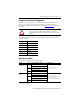
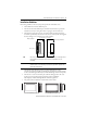
Industrial Computers for Hazardous Locations 7 Product Options This table summarizes the product options available for the industrial integrated display computers. Cat. No. Series Display Size Touchscreen Package 6181X-NPXPDC F Non-display N/A Performance 12.1 in. Yes Performance 6181X-12TPXPDC This table summarizes the product accessories options available for the industrial integrated display computers. Cat. No.
Industrial Computers for Hazardous Locations Multilingual User Interface CD Pack The Microsoft Multilingual User-interface (MUI) CD Pack contains a collection of different language sets that can be installed into the operating system. The primary language is English. Languages pre-installed on computers with a hard disk drive include: Chinese, French, German, Japanese, Italian, Spanish, and Portuguese.
Industrial Computers for Hazardous Locations 9 Installation Guidelines Follow these guidelines to make sure your product provides safe and reliable service: • The installation site must have sufficient power. • The enclosure must allow sufficient space around air inlets and outlets to provide the circulation necessary for cooling. Never allow air passages to become obstructed. • The ambient air temperature must not exceed the maximum operating temperature.
Industrial Computers for Hazardous Locations Mounting Clearances When selecting an installation site for the computers, be sure to allow adequate clearance on the sides and rear of the computer for proper ventilation, cable connection, and hardware access. Sufficient airflow throughout the system unit is required to maintain proper cooling. Clearance should be enough to allow convenient installation or removal of peripheral components, such as the CompactFlash card.
Industrial Computers for Hazardous Locations 11 Product Dimensions Product dimensions for the computers are given in mm (in.). 251.00 (9.88) 190.50 (7.5) 57.50 (2.26) 11.30 (0.44) 83.40 (3.28) 335.28 (13.20) 238.18 (9.37) 353.00 (13.90) 1.60 (0.06) Non-display Computer, Catalog Number 6181X-NPXPDC Integrated Display Computer, Catalog Number 6181X-12TPXPDC 320.00 (12.60) 101.30 (3.99) 75.40 (2.97) 14.50 (0.57) 115.00 (4.53) 115.00 (4.53) 251.00 (9.88) 279.00 (10.98) 349.00 (13.
Industrial Computers for Hazardous Locations Install the Computer The computers support these mounting options. Cat. No. Computer Model Mounting Option 6181X-NPXPDC Non-display Wall mount Display Panel mount (1) 6181X-12TPXPDC (1) Display computers must be securely mounted by using all mounting clips. Mount the Non-display Computer on a Wall Four mounting screws secure the non-display computer to a metal wall, such as a steel mounting panel in an enclosure or equipment room.
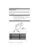
Industrial Computers for Hazardous Locations 13 Mount the Display Computer in a Panel Mounting clips secure the 6181X-12TPXPDC display computer to the panel. Make sure to mount the computer vertically. Panel Mounting Guidelines Observe these guidelines when installing the unit in a panel: • Remove all electrical power from the panel before making the cutout. • Confirm that there is adequate space behind the panel. For specific information refer to Mounting Clearances on page 10.
Industrial Computers for Hazardous Locations 4. Slide the mounting clips into the holes on the top, bottom, and sides of the computer. 5. Gradually tighten the clips, one at a time, around the bezel by using the specified sequence starting with the center clips and continuing to the corner clips. 9 1 10 5 3 4 6 8 2 7 6. Tighten the mounting clips to a torque of 1.4 N•m (12 lb•in) by using the sequence in step 5, being sure not to overtighten.
Industrial Computers for Hazardous Locations 15 Hardware Features The illustrations show the hardware features of the display industrial computers for hazardous locations.
Industrial Computers for Hazardous Locations Bottom View, Catalog Number 6181X-12TPXPDC Item Component 1 Serial COM ports, 2 2 Ethernet ports (RJ-45), 2 3 DVI-I port 4 PCI riser slot cover 5 Power switch 6 DC input terminal block 7 Functional ground screw 8 Hinged door covering the USB ports, 4(1) 9 External CompactFlash Type II card slot(1) (1) This bottom side external CF slot and USB ports are functionally hot-pluggable in an environment known to be non-hazardous.
Industrial Computers for Hazardous Locations 17 Control Drawing - Class I Division 2 and Zone 2 Required Circuit Parameters for USB Peripheral Devices The following control drawing is provided in accordance with the National Electrical Code, Article 500 (Class I, Zone 2, Group IIB and Class I, Division 2, Groups A, B, C and D).
Industrial Computers for Hazardous Locations Application Information The circuit parameters of associated field-wired apparatus for use in hazardous locations shall be coordinated with the host product such that their combination remains nonincendive. The 6181X computers and the USB peripheral devices shall be treated in this manner. The circuit parameters of the 6181X computers’ USB ports are indicated in the previous table. The 6181X computers provides four separately powered USB ports.
Industrial Computers for Hazardous Locations 19 Follow these steps to connect the computer to a DC power source. 1. Verify the main power switch or breaker is off. 2. Verify that the DC power wires meet these requirements: – Material: Stranded copper – Wire gauge: 14…18 AWG 3. Secure the DC power wires to the terminal block screws. 6181X-12TPXPDC Display Computer Shown -V +V -V +V Tighten the terminal to a torque of 0.687 N•m (6.1 lb•in). 4.
Industrial Computers for Hazardous Locations Connect to a Network The computers have two Gigabit LAN ports. The computers connect to an Ethernet network by using CAT5 or CAT5E twisted-pair Ethernet cabling with RJ-45 connectors. 6181X-12TPXPDC Display Computer 6181X-NPXPDC Non-display Computer ATTENTION: When connecting a LAN cable, make sure the cable is fully inserted in the LAN port and that the latch is engaged.
Industrial Computers for Hazardous Locations 21 Component Replacement When installing hardware or performing maintenance procedures requiring access to internal components, we recommend that you first back up all computer data to avoid loss. IMPORTANT To prevent voiding your product warranty, use only Rockwell Automation Allen-Bradley approved replacement parts and accessories. You can view a current list of accessories at the Rockwell Automation website http://www.ab.com/industrialcomputers.com.
Industrial Computers for Hazardous Locations Rear Cover Follow these steps to remove the rear cover. 1. Disconnect power from the computer. 2. Loosen the three screws that secure the rear cover (1). 3. Open the cover and detach it from the chassis (2). 6181X-12TPXPDC Display Computer Follow these steps to reinstall the rear cover. 1. Fasten the rear cover to the chassis (1). 2. Tighten the three screws to secure the rear cover (2).
Industrial Computers for Hazardous Locations 23 CompactFlash Card IMPORTANT Use only catalog numbers 6189V-CFSSD8GB and 6189V-CFSSD16GB CompactFlash (CF) cards in the 6181X industrial computers for hazardous locations. Other replacement cards are not acceptable for use in hazardous locations. The computers have two CompactFlash (CF) Type II card slots: • Internal CF slot (right side) – A card installed in this slot is considered bootable and is designed to function as a main hard disk drive.
Industrial Computers for Hazardous Locations Load a CF Card in the Internal CF Card Slot Follow these steps to load a CF card in the internal CF card slot. 1. Disconnect power from the computer. 2. Loosen the screw that secures the CF card slot cover (1), then the screw that secures the CF card slot lever (2). 3. Extend the CF card slot lever (3), then pull out the CF card tray (4). 4. Remove the CF card lock screw (5). If necessary, remove existing CF card by sliding it out of the slot. 5.
Industrial Computers for Hazardous Locations 25 PCI Add-in Card IMPORTANT When used in hazardous locations the computer supports peripheral cards rated 4 W maximum, and Class I, Division 2, Groups A, B, C, D, T4. In Europe, use in ATEX Group IIC Category 3 gas and dust environments is supported. At maximum product temperature a PCI card dissipating 4 W may experience a surrounding air temperature up to 90 °C (194 °F).
Industrial Computers for Hazardous Locations Memory Module The computers have two dual-channel DDR II DIMM slots that support up to 4 GB maximum system memory. Note that Microsoft Windows operating system limits the maximum usable capacity to approximately 3 GB. IMPORTANT Use only catalog number 6189X-4GDDR2 in the 6181X industrial computers for hazardous locations. Other memory modules are not acceptable for use in hazardous locations.
Industrial Computers for Hazardous Locations 27 5. Completely open the retaining latches securing the memory module (1). This forces the module up in the slot and makes it easier to remove. 6. Gently remove the memory module from its slot (2). 6181X-12TPXPDC Display Computer 7. Place the memory module on a static-dissipating work surface or inside an antistatic bag. 8. Hold the new memory module by its edge and remove it from its protective packaging. 9.
Industrial Computers for Hazardous Locations 11. Fasten a replacement cable tie around the DIMM slot latches (1). IMPORTANT Reinstalling the cable tie is required to meet hazardous locations, mechanical shock, and vibration requirements. 12. Pull the end of the cable tie to lock it in place (2). 13. Cut the excess length of the cable tie. 14. Repeat steps 4…13 for DIMM2 slot if a second memory module is installed. 15. Reinstall the rear cover. 16. Apply power to the computer.
Industrial Computers for Hazardous Locations 29 At the end of its life, the battery contained in this product should be collected separately from any unsorted municipal waste. The collection and recycling of batteries helps protect the environment and contributes to the conservation of natural resources as valuable materials are recovered. Remove the Battery Follow these steps to remove the RTC battery for proper disposal. 1. Disconnect power from the computer. 2. Remove the rear cover. 3.
Industrial Computers for Hazardous Locations Technical Specifications - 6181X-NPXPDC, 6181X-12TPXPDC Attribute 6181X-NPXPDC, 6181X-12TPXPDC Processor Intel Core Duo U2500, 1.2 GHz/2M L2 cache/533 MHz 9 W System chipset Intel 945GME, ICH7-M Ethernet LAN 2 GB LAN ports (RJ45) System memory 2 GB shipped, 4 GB max Display Display type Active Matrix Color TFT Touch screen Resistive, sunlight readable Display size (diagonal) 308 mm (12.1 in.
Industrial Computers for Hazardous Locations 31 Technical Specifications - 6181X-NPXPDC, 6181X-12TPXPDC Attribute Relative humidity Altitude, operating Altitude, nonoperating Shock, operating Shock, nonoperating Vibration, operating 6181X-NPXPDC, 6181X-12TPXPDC 10…90% noncondensing 2,000 m (6,561 ft) 12,000 m (40,000 ft) 15 g (1/2 sine, 11 ms) 30 g (1/2 sine, 11 ms) 0.012 in.
Rockwell Automation Support Rockwell Automation provides technical information on the Web to assist you in using its products. At http://www.rockwellautomation.com/support/, you can find technical manuals, a knowledge base of FAQs, technical and application notes, sample code and links to software service packs, and a MySupport feature that you can customize to make the best use of these tools.