RAC 6181 and VersaView 6181P-10, -12 Industrial Computers User Manual
Important User Information Solid state equipment has operational characteristics differing from those of electromechanical equipment. "Safety Guidelines for the Application, Installation, and Maintenance of Solid State Controls" (Publication SGI-1.1) describes some important differences between solid state equipment and hard-wired electromechanical devices.
Table of Contents Using this Manual Preface Who Should Use This Manual .................................................. P-1 Purpose of this Manual.............................................................. P-1 Contents of this Manual ............................................................ P-2 Manual Conventions ................................................................. P-3 Allen-Bradley Support ..............................................................
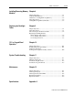
toc-ii Table of Contents Initial Operation and Setup Chapter 3 Chapter Objective ...................................................................... 3-1 Operating Recommendations..................................................... 3-1 Operator Access ......................................................................... 3-1 System Checkout ....................................................................... 3-2 System Reset........................................................................
Table of Contents toc-iii Installing/Removing Memory Chapter 8 Modules Chapter Objective.......................................................................8-1 Available RAM Memory............................................................8-1 Guidelines for Adding/Removing Memory................................8-2 Safety Precautions ......................................................................8-3 Adding/Removing Memory Modules ........................................
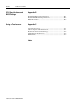
toc-iv Table of Contents CPU Specifications and BIOS Settings Using a Touchscreen Appendix B Pentium® CPU Card Specifications..........................................B-1 Pentium III CPU Card Specifications........................................B-2 BIOS Information ......................................................................B-3 Appendix C Appendix Overview...................................................................C-1 6181 Computers with Touchscreen....................................
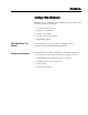
Preface Using this Manual Read this preface to familiarize yourself with the rest of the manual. The preface covers the following topics: • who should use this manual • the purpose of the manual • contents of the manual • conventions used in this manual • Allen-Bradley support Who Should Use This Manual Use this manual if you are responsible for installing, using, or troubleshooting the RAC6181 Industrial Computer. Purpose of this Manual This manual is a user guide for the RAC6181 Industrial Computer.
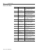
P–2 Using this Manual Contents of this Manual Chapter Publication 6181-UM001D-EN-P Title Contents Preface Describes the purpose, background, and scope of this manual. Also specifies the audience for whom this manual is intended. 1 System Features Shows the different versions of the RAC6181 Computer and system features. 2 Installation Describes how to install the RAC6181 Computer in a panel or enclosure. Also tells how to connect devices (such a mouse/keyboard) to the system.
Using this Manual Manual Conventions P–3 The following conventions are used throughout this manual: • Bulleted lists such as this one provide information, not procedural steps. • Numbered lists provide sequential steps or hierarchical information.
P–4 Using this Manual Publication 6181-UM001D-EN-P
1 Chapter System Features Chapter Objectives This chapter provides an overview of the RAC6181 Industrial Computer including: • available versions • software • additional catalog items RAC6181 Computer Versions The following table summarizes the options for each version: Table A RAC6181 Computer Product Options 10.4-inch Display 12-inch Display 12-inch Display with Keypad Processor Board x x x x Hard Drive x x x x 1.
1–2 System Features RAC6181 Computer Packing List The RAC6181 Computer is delivered with the following items: • Computer • Mounting nuts (10, 8 required) or mounting clips (6) (12 in.
System Features Features of the RAC6181 Computer 1–3 The following illustrations show the major features and controls of the display versions of the RAC6181 Computer.
1–4 System Features RAC6181 Computer - Non-Display Version RAC6181 Computer Connectors – 2 Slot Chassis * The maximum processor speed available for 2-slot chassis is the Pentium III 600MHz option.
System Features 1–5 RAC6181 Computer Connectors – 4 Slot Chassis I/O Card CPU Card PCI Expansion Slots (2) Video Port (HD-15) Shared PCI/ISA Expansion Slot* Backlight Dimming Control (Display Versions Only) ISA Expansion Slot Serial Port 1 (DB9) 2 USB Ports Ethernet Connector (RJ45) PS/2 Keyboard Connector (Mini Din) Parallel Port (DB25) 3.5" Hard Drive (Internal) PS/2 Mouse Connector (Mini Din) 3.
1–6 System Features LED Indicators The following tables show the LED indicators on the RAC6181 Computer. Standard units have symbol indicator labels. Units with the optional stainless steel bezel have no labels. Table B LED Indicators (Display Versions Only) Indicator Position Left Color Red Indicates Diagnostics. Indicates that one of the following conditions exists: • Overtemperature. Temperature inside the RAC6181 Computer enclosure is above defined threshold. • Fan Sensor.
System Features Backlight Dimming Control 1–7 Use the backlight dimming control to vary the screen lighting for optimum viewing. Turn the control clockwise to increase display backlight brightness. Turn it counter-clockwise to dim the display backlight. Hazardous Location Certification Specific configurations of the RAC6181 Computer are certified for Class I, Division 2, Groups A, B, C, D, T4A temperature code, hazardous areas.
1–8 System Features Publication 6181-UM001D-EN-P
Chapter 2 Installation Chapter Objective This chapter describes installation of the RAC6181 Industrial Computer including how to install the RAC6181 Computer in a panel using mounting studs or clips. European Union Compliance The RAC6181 Computer meets the European Union Directive requirements when installed within the European Union or EEA regions and has the CE mark. A copy of the Declaration of Conformity is available at the Rockwell Automation / Allen-Bradley Internet site: www.ab.
2–2 Installation Mounting Hardware Versions of the RAC6181 Computer with a display are shipped with one of the following types of mounting hardware: Table D Mounting Hardware Item Description Self-locking nuts (#10-32) Mounting clips Tools Required Quantity Use For 10 (8 required) Panel or enclosure mounting (display version) 6 Panel or enclosure mounting (display/keypad version) In addition to the tools required to make the cutout, you will need the following tools: For Mounting Studs: • 3/8 in
Installation Mounting Clearances 2–3 Allow adequate space for mounting, air flow, and maintenance. The figure below shows recommended minimum clearances to other components within the rack or enclosure. ATTENTION: The RAC6181 Computer should not be operated within a confined space of the dimensions shown below unless adequate ventilation or other cooling methods are used to lower the air temperature within the enclosure.
2–4 Installation Mounting Dimensions The following figures show the mounting dimensions for the RAC6181 Computer. 10.4 in. Version with Display 2-Slot Version (Side View) 4-Slot Version (Side View) 181.71 [7.154] 231.55 [9.
Installation 2–5 12.1 in. Version with Display 2-Slot Version (Side View) 4-Slot Version (Side View) 189.64 [7.466] 231.55 [9.
2–6 Installation 12.1 in. Version with Keypad and Display 2-Slot Version (Side View) 143.34 [5.643] 254.76 [10.030] Publication 6181-UM001D-EN-P 4-Slot Version Height: 254.76 [10.030] Depth: 173.02 [6.
Installation 2–7 Non-Display Version 2-Slot Version 4-Slot Version Height: 231.7 [9.125] Depth: 153.44 [6.
2–8 Installation RAC6181 Industrial Computer with Expansion Bay Option The following figures show the mounting dimensions for the RAC6181 Computer with expansion bay option installed. The expansion bay option is valid for any RAC6181 enclosure option.
Installation 10.4 in. Mounting Cutout 2–9 The following figure provides the dimensions for making the panel or enclosure cutout for the 10.4 in. RAC6181 Computer.
2–10 Installation 12.1 in. Mounting Cutout Publication 6181-UM001D-EN-P The following figure provides the dimensions for making the panel or enclosure cutout for the 12.1 in. RAC6181 Computer.
Installation 12.1 in. with Keypad Mounting Cutout 2–11 The following figure provides the dimensions for making the panel or enclosure cutout for the 12.1 in. RAC6181 Computer with keypad.
2–12 Installation Panel Mounting with Mounting Studs To install the RAC6181 Computer in a panel using 8 mounting studs: ATTENTION: Disconnect all electrical power from the panel before making cutout. Make sure the area around the panel cutout is clear. Take precautions so that metal cuttings do not enter any components that are already installed in the panel. Failure to follow these warnings may result in personal injury or damage to the panel components.
Installation Panel Mounting with Mounting Clips 2–13 To install the RAC6181 Computer in a panel using mounting clips: ATTENTION: Disconnect all electrical power from the panel before making cutout. Make sure the area around the panel cutout is clear. Take precautions so that metal cuttings do not enter any components that are already installed in the panel. Failure to follow these warnings may result in personal injury or damage to the panel components.
2–14 Installation 5. Gradually tighten the clips one at a time around the bezel using the specified sequence. Repeat this process at least three times until the clips are hand-tight and the gasket is compressed uniformly against the panel. 6. Tighten mounting clips to a torque of 10 in–lbs (1.1 N•m) in the sequence shown above. Do not over–tighten. ATTENTION: Tighten mounting clips to a torque of 10 in–lbs (1.1 N•m) to provide a proper seal and prevent damage to the RAC6181 Computer.
Installation 2–15 Peripheral Devices ATTENTION: Peripheral devices attached to the RAC6181 Computer should not be operated in the presence of possible hazardous materials, unless that specific device is rated for Class I, Div 2 environments. Example devices are external keyboard, external mouse products, and external removable media drives. Connecting a Mouse & Keyboard (Side Panel) The mouse and keyboard plug into the side panel mouse and keyboard ports as shown below.
2–16 Installation Connecting a Mouse & Keyboard (12.1 in. keypad version) The 12.1 in. front keypad is jumpered to the CPU board keyboard port. An external keyboard can be connected and used as shown below. When connected as shown below, both the front keypad and the external keyboard can be used simultaneously. Make sure this does not cause any unsafe operating conditions. 6189-PS2JUMPER cable required to connect bezel keypad to the CPU board.
Installation AC Power Connections 2–17 A standard IEC 320 power cord provides power to the RAC6181 Computer AC version. The power supply input will accept 120/240V AC. The power supply is autoswitching. ATTENTION: The power cord must be connected to an outlet having an earth ground (three-prong outlet). Failure to follow this warning could result in severe electrical shock. Use the power cord retainer to prevent accidental interruption of power to the RAC6181 Computer.
2–18 Installation DC Power Connections A standard three position terminal block is provided for connecting power. Use 12 or 14 AWG stranded wire to connect these terminals to a stable source of 24V DC power with 10A minimum rating available. Observe proper polarity and keep the wiring as short as possible (recommend less than 3 meters). Ensure that the wires are connected correctly using standard wiring practices. Twist the wires 1-3 twists per inch.
Chapter 3 Initial Operation and Setup Chapter Objective This chapter provides information on: • operating recommendations • boot-up sequence • system reset and Power On Self Test (POST) • Universal Serial Bus (USB) • Windows NT networking • Windows 2000 touchscreen driver installation Operating Recommendations We recommend the following operating guidelines for the RAC6181 Computer: • Avoid turning the system on and off frequently.
3–2 Initial Operation and Setup System Checkout To boot up the system: 1. Apply power to the computer. The RAC6181 Computer performs a Power On Self Test (POST) in which it tests the processor board, memory, keyboard, and certain peripheral devices. 2. The RAC6181 Computer displays the progress of the POST and initialization of accessory devices. 3. If your system does not boot up, or you notice other problems, refer to Chapter 11, System Troubleshooting. 4.
Initial Operation and Setup Using USB 3–3 The RAC6181 Computer has two USB connectors. The Universal Serial Bus (USB) is an external bus standard that supports data transfer rates of 12Mbps (12 million bits per second). A single USB port can connect multiple peripheral devices, such as mice, modems, and keyboards. USB also supports Plug-and-Play installation and hot plugging. For more information on installing or using USB, refer to the documentation for your USB peripheral device.
3–4 Initial Operation and Setup Publication 6181-UM001D-EN-P
Initial Operation and Setup 3–5 Initial Startup and Service Packs The initial system startup begins with the NT operating system at Service Pack 1, and enters Window NT Workstation Setup. During setup, the system is built, the drivers and applications are installed, user information is gathered via the start-up dialogs. At the end of setup, the current Service Pack is automatically installed and is visible when the system is restarted.
3–6 Initial Operation and Setup Touchko Touch Screen Application The 6181 12.1 inch keypad bezel computer uses a Touchko WIN32 touchscreen application instead of an operating system driver. This means the touchscreen is not active until after the operating system is completely booted. This application is factory configured to automatically start during the operating system boot. It is placed in the appropriate start-up folder for the Windows operating system.
Initial Operation and Setup 3–7 Publication 6181-UM001D-EN-P
Chapter 4 Adding/Removing System Components Chapter Objectives This chapter describes how to remove and install: • back cover and top cover • add-in cards • CPU card Note: Instructions for removing and installing additional components are included in additional chapters of this manual: • Chapter 5, Installing/Removing the Power Supply • Chapter 6, Installing/Removing the Hard Drive, Floppy Drive, or Expansion Bay • Chapter 8, Installing/Removing Memory Modules Safety Precautions The RAC6181 Computer c
4–2 Adding/Removing System Components Hazardous Locations Specific configurations of the RAC6181 Computer are certified for Class I, Division 2, Groups A, B, C, D, T4A temperature code, hazardous areas. If you are using the RAC6181 in a hazardous location, review the following safety considerations: ATTENTION: EXPLOSION HAZARD! Do not connect or disconnect equipment while circuit is live unless area is known to be non-hazardous.
Adding/Removing System Components Removing the Back Cover and Top Cover 4–3 This section shows how to remove the back cover and top cover to access internal components. Note: The 2-slot chassis is used in the following diagrams. Similar procedures apply to the 4-slot chassis. ATTENTION: Review safety precautions on Page 4-1 before proceeding. Failure to follow proper safety procedures could result in severe electrical shock or damage to the RAC6181 Computer. To remove the back cover or top cover: 1.
4–4 Adding/Removing System Components 3. To re-install the back cover, position the back cover over the chassis and tighten the screws. Align the two pins on the inside of the back cover that secure the hard drive bay. ATTENTION: Be careful not to push the vibration dampers (grommets) on the drive bay out of the sheet metal. Note: If the unit is equipped with the optional expansion bay, ensure that the cables connecting the drive to the CPU card are positioned correctly.
Adding/Removing System Components 4–5 To remove a slot cover (to add a board): 1. Remove the top cover. See Page 4-3. 2. Locate the slot cover you want to remove. 3. Remove the screw securing the slot cover and remove the cover. 2-slot version 4-slot version ISA Slot Shared PCI/ISA Slot PCI Slots Slot Cover CPU I/O Slot CPU Slot Screw To install a slot cover (after removing a card): 1. Insert the end of the cover into the slot in the chassis. 2.
4–6 Adding/Removing System Components To install a CPU or add-in card: 1. Remove the board from its anti-static packaging and place on a grounded, static free surface. 2. Set any board jumpers or switches as described in the instructions for the board. Note: If you are replacing the CPU card, make careful note of the cables attached to the existing CPU card so that you can reconnect the cabling to the new card.
Adding/Removing System Components 4–7 3. Hold the board by the edges and firmly press the board into the connector on the processor board. Note: Be careful not to disturb the air flow director. It is required to keep the CPU cool. The flow director for the 2-slot chassis should be routed behind the two add-in card slots and extend alongside the CPU heat sink. 4. Align the notch in the board retainer with the threaded hole and install the screw.
4–8 Adding/Removing System Components To remove a CPU or add-in card: 1. Remove the screw securing the board retainer. 2. Hold the board at each end and carefully rock the board back and forth until the edge connectors pull free. Note: When removing the CPU card: • Carefully remove all connecting wiring. Make notes of the location of all connectors to ensure that you can properly reconnect the wiring. 3. Store the board in an anti-static wrapper. 4. Remove any unused cable associated with the board. 5.
Chapter 5 Installing/Removing the Power Supply Chapter Objective This chapter provides instructions on how to remove or install a RAC6181 Industrial Computer power supply (AC or DC version). Removing the power supply involves the following procedures: • Disconnecting the cables from six devices that are connected to the existing power supply (this requires partially removing the CPU card).
5–2 Installing/Removing the Power Supply Installing/Removing a Power Supply The power supply for the RAC6181 Industrial Computer accepts an input power and provides regulated lower voltages required for all internal components such as the processor board, card connectors, and chassis fan. The RAC6181 Computer has the following power supply options: • AC power version with a 120/240V AC power supply. • DC power version with an 18-32 V DC power supply.
Installing/Removing the Power Supply 5–3 4. Remove the 4 mounting screws that secure the power supply (2-slot chassis shown below). 5. Remove the power supply. 6. Disconnect the cables that connect the power supply to the input terminal strip: • With the AC option, disconnect the cables from the bottom of the power supply. • With the DC option, disconnect the red and black cables from the input terminal strip itself. Cut the tie strips that secure these cables around the fan.
5–4 Installing/Removing the Power Supply To install the power supply (AC option): ATTENTION: Risk of Electrical Shock. Do not use screws exceeding 6.35mm (0.25 inches). Screws that are longer than recommended may come in contact with voltage sources within the power supply. 1. Connect the input cables to the bottom of the power supply. 2. Position the power supply in the chassis and secure with the 4 mounting screws. Torque screws to 0.7 to 0.9 N-m (6-8 in-lbs). 3.
Installing/Removing the Power Supply 5–5 To install the power supply (DC option): 1. Connect the two cables from the bottom of the power supply and fuse assembly to the appropriate connectors on the input terminal strip. The red cable connects to +24V DC terminal. The black cable connects to the 0V DC middle terminal. (For an illustration of the DC power connection, refer to Page 2-19.) 2. Using the supplied tie strips, secure the cables from the terminal strip around the base of the fan. 3.
5–6 Installing/Removing the Power Supply 4. Connect the power supply cable connectors to the processor board and other internal components. The connectors are keyed so they cannot be installed the wrong way, do not force connectors. ATTENTION: Make sure the air flow director is properly positioned. Failure to correctly install the flow director may result in excessive temperatures that can damage the RAC6181 Computer. 2-Slot Chassis 4-Slot Chassis 5. Install the back and top cover.
Chapter 6 Installing/Removing the Hard Drive, Floppy Drive, or Expansion Bay Chapter Objective This chapter describes how to install or remove the floppy drive and a hard disk from the RAC6181 Industrial Computer and how to install or remove the optional expansion bay. Available Drives The RAC6181 Computer supports the following disk drives: Disk Drive Safety Precautions Catalog No. Standard EIDE 3.5” hard disk 6189–HD300 Large EIDE 3.5” hard disk 6189–HD600 1.
6–2 Installing/Removing the Hard Drive, Floppy Drive, or Expansion Bay Installing/Removing a Hard Drive or Floppy Drive These instructions describe how to remove the drive bay and replace the hard drive or floppy drive. To remove the drive bay: 1. Disconnect power from the RAC6181 Computer. ATTENTION: Disconnect all power from the RAC6181 Computer before adding or removing components. Failure to disconnect power could result in severe electrical shock or damage to the RAC6181 Computer. 2.
Installing/Removing the Hard Drive, Floppy Drive, or Expansion Bay 6–3 To install the drive: 1. Install the hard drive in the drive bay (4 screws) 2. Connect the ribbon cable connector and power cables to the hard drive and floppy drive. Note: Make sure that the ribbon cable is installed correctly. The connector must be positioned so that the red wire of the cable is closest to the back of the unit. 3.
6–4 Installing/Removing the Hard Drive, Floppy Drive, or Expansion Bay Replacing the floppy drive in the hard drive bay: 1. Perform the steps to disconnect and remove the hard drive bay on Page 6-2. 2. Remove the four floppy drive mounting screws, loosen the hard drive mounting screws, and slide the drive from the drive bay. Note: The floppy drive and hard drive screws require different tool bits. 3.
Installing/Removing the Hard Drive, Floppy Drive, or Expansion Bay Installing/Removing an Expansion Bay 6–5 These instructions describe how to install the optional 5.25-in. drive expansion bay (6189-1EXPBAY) on the RAC6181 Computer. The expansion bay can be used to house additional components such as a DVD-ROM or Read/Write CD-ROM drive.
6–6 Installing/Removing the Hard Drive, Floppy Drive, or Expansion Bay 7. Disconnect the existing power cable attached to the hard drive. 8. Connect the power cable to the appropriate connector of the Y-shaped power cable provided with the expansion bay kit. Connect the other connector to the hard drive. 9. Leave hard drive jumper in default setting (Master). 10. Position the drive bay into the chassis so that the studs on the chassis fit into the grommets on the drive bay.
Installing/Removing the Hard Drive, Floppy Drive, or Expansion Bay 6–7 To install the drive in the expansion bay: 1. Feed the power cable and ribbon cable through the slot on the bottom of the expansion bay. 2. Connect the power cable and ribbon cable to the expansion drive. Note: If you are installing a CD-ROM drive, ensure that the jumper setting on the CD-ROM drive is set to "Slave." 3. Secure the drive to the expansion bay using the four screws provided.
6–8 Installing/Removing the Hard Drive, Floppy Drive, or Expansion Bay 3. Carefully remove the expansion bay. Note: Depending on the expansion drive installed, the cables connecting the drive may be short. Be sure not to damage the drive or the connections. 4. If necessary, disconnect the ribbon cable connector and the power connector from the expansion drive.
Chapter 7 Connecting External Drives Chapter Objective This chapter shows how to connect an external drive to the RAC6181 Industrial Computer. Note: Safety Precautions Refer to Chapter 6 for instructions on installing the optional expansion bay for internal drives. Observe the following precautions when connecting an external drive: • Always handle the media by its case. • Avoid touching the cable connectors. • Remove disks before disconnecting power to the drive.
7–2 Connecting External Drives Connecting an External Drive This section gives instructions for connecting an external drive to the RAC6181 Computer. 1. Before you apply power to the RAC6181 Computer, connect the parallel connector for the external drive to the parallel port on the RAC6181 Computer. For drives supporting a USB interface, connect the drive to the USB port on the RAC6181 Computer. 2. Connect the AC plug for the external drive to a power source. 3. Connect power to the RAC6181 Computer. 4.
Chapter 8 Installing/Removing Memory Modules Chapter Objective This chapter describes how to add RAM Memory to the RAC6181 Computer processor board.
8–2 Installing/Removing Memory Modules Guidelines for Adding/Removing Memory (Pentium CPU Card) When adding memory to the RAC6181 Pentium processor board, follow these guidelines: • Use only a standard, unbuffered 168–pin DIMM that conforms to both PC-100 and Serial Presence Detect (SPD) compliance industry standards. • Use only Synchronous Dynamic Random Access Memory (SDRAM) type DIMMs. • BIOS automatically detects memory size and type (i.e., SDRAM vs. EDO).
Installing/Removing Memory Modules Safety Precautions 8–3 Internal RAC6181 Computer components may be damaged by Electrostatic Discharge (ESD). Make sure you wear a grounding strap whenever handling circuit boards, memory modules or other internal components. ATTENTION: Wear a wrist strap (well grounded) and perform work in a static-safe environment. Electrostatic discharge can damage the RAC6181 Computer and components.
8–4 Installing/Removing Memory Modules 4. To install a new DIMM, hold the module only by the edges as you remove it from its anti–static package. 5. Position the DIMM so that the small notches in the bottom edge of the DIMM align with the notches in the DIMM socket on the CPU card. The retaining latch should be fully disengaged when attempting to install a DIMM. 6. Press down firmly and uniformly on the DIMM to seat it in the socket.
Chapter 9 Replacing the Backlight Tubes Chapter Objective This chapter describes how to replace the backlight tubes on the RAC6181 Computer flat panel display. Topics include: • Disconnecting the touchscreen cable • Removing the flat panel display • Replacing the backlight tubes Safety Precautions The RAC6181 Computer contains line voltages. Make sure you disconnect all power to the RAC6181 Computer before performing any of the operations described in this chapter.
9–2 Replacing the Backlight Tubes Disconnecting the Touchscreen Cable (Display-Only Versions) RAC6181 Industrial Computer 10.4-in. and 12.1-in. display-only versions may come equipped with a touchscreen. If so, you will have to disconnect the touchscreen cable before removing the flat panel display and replacing the backlight tubes. Disconnecting the touchscreen cable: 1. Remove the back cover of the RAC6181 Computer. Refer to “Removing the Back Cover and Top Cover” on page 4-3 for complete instructions.
Replacing the Backlight Tubes Replacing the Backlight Tubes (10.4-in. DisplayOnly Version) 9–3 Removing the flat panel display: 1. Remove the 10 screws that secure the flat panel to the RAC6181 Computer chassis. 2.
9–4 Replacing the Backlight Tubes 3. Lift and pivot the chassis to the left. If you have a touchscreen unit, make sure the touchscreen cable comes out of the chassis without becoming snagged and damaged. Place the chassis on its edge to the left of the unit. 4. On the flat panel display, disconnect the backlight tube connectors from the backlight power supply. 5. Disconnect the display cable from the flat panel display by removing the 3 screws holding it to the small printed circuit board on the display.
Replacing the Backlight Tubes 9–5 3. Place the chassis back onto the display assembly while: • Reattaching the LED connector to the LED board • Reattaching the power cable to the backlight controller board • Threading the touchscreen cable (if necessary) back into the chassis 4. Reattach the touchscreen cable to the touchscreen controller board, if necessary. 5. Reattach the display assembly to the unit using the 10 screws. 6. Replace the back cover of the unit if necessary.
9–6 Replacing the Backlight Tubes 5. Pivot the chassis to the left. If you have a touchscreen unit, make sure the touchscreen cable comes out of the chassis without becoming snagged and damaged. 6. Lift and pivot the chassis off of the display assembly and place the chassis on its side to the left of the display assembly. 7. Disconnect the display cable from the flat panel display by removing the 2 screws holding it to the small printed circuit board on the display (see figure below).
Replacing the Backlight Tubes 9–7 4. Replace the screws that hold the backlight in place. Reinstalling the flat panel display: 1. Reattach the display cable to the flat panel display by gently plugging the connector into the small printed circuit board and replacing the 2 screws that hold it in place. ATTENTION: Do not overtighten the screws holding the display cable to the printed circuit board. Tighten to a torque of 1-2 in-lbs. (0.1-0.2 N-m). 2.
9–8 Replacing the Backlight Tubes Replacing the Backlight Tubes (12.1 in. Keypad Version): Removing the flat panel display 1. Remove the 6 screws that secure the flat panel to the RAC6181 Computer chassis. Screws securing flat panel Retaining screw Hinged chassis Flat panel display 2. Remove the retaining screw from just below the top hinge and open the hinged chassis enough to remove the chassis from the display assembly. Place the chassis on its side to the right of the display assembly. 3.
Replacing the Backlight Tubes 9–9 Replacing the backlight tubes: 1. Remove the 2 screws holding each backlight tube in place. Backlight Screws Backlight Retaining Tabs Backlights are shaded in gray. Display Cable Retaining Screws Backlight Screws 2. Slide the tube to the right about 1/8 in. (3 mm) and gently pull the tube up and out of the assembly. 3. Insert the replacement backlight tube into the slot and slide it to the left until the holes for the screws are aligned. 4.
9–10 Replacing the Backlight Tubes 3. Reattach the display cable to the flat panel display by gently plugging the connector into the small printed circuit board and replacing the 2 screws that hold it in place. ATTENTION: Do not overtighten the screws holding the display cable to the printed circuit board. Tighten to a torque of 1-2 in-lbs. (0.1-0.2 N-m) 4. Reattach the display assembly to the unit using the 6 screws. 5. Replace the retaining screw below the top hinge.
Chapter 10 12.1 in. Keypad Bezel Operation Chapter Objective This chapter describes operations specific to the RAC6181 12.1 in. keypad version. The RAC6181 front bezel assembly consists of a plastic bezel with overlay and a metal frame assembly that holds the LCD panel and associated interconnection circuit boards. The RAC6181 keypad version has removable function key legend strips.
10–2 12.1 in. Keypad Bezel Operation To replace the horizontal legend strip: 1. Locate the exposed legend strip tab on the lower left side of the RAC6181 unit. Horizontal Legend Strip Tab 2. Carefully pull on the tab to remove the installed legend strip. 3. To insert the new legend strip, first slightly cup the strip and carefully push it into the bezel slot. Short pushes will help slide the new strip fully into place. 4. Verify the alignment of the legend strip text with the front overlay key windows.
12.1 in. Keypad Bezel Operation 10–3 To replace the vertical legend strips: 1. Remove the RAC6181 from the panel. 2. Remove the 6 adapter plate screws and open the hinged front (page 9-8). 3. Disconnect all cables between the bezel and computer chassis. 4. Close bezel to access the hinges on the outside of the unit. Remove the screw retaining the hinge halves together. This will allow you to separate the bezel from the chassis. 5. Separate the bezel assembly completely from the chassis. 6.
10–4 12.1 in. Keypad Bezel Operation 12. To reassemble the front bezel assembly, thread the keypad and touchscreen cables through the hole in the metal frame. 13. Reconnect the keypad cable, touchscreen cable, backlight tube connectors, and backlight power supply cable. 14. Reinstall the 10 screws to attach the metal frame to the plastic overlay assembly. Tighten the screws to a torque of 6 – 8 in-Lbs (0.7 – 0.9 N•m). 15. Attach the bezel and install the hinge retainer screw. 16.
12.1 in. Keypad Bezel Operation 10–5 System Requirements The RAC6181 Keypad Configuration Utility is a 32-bit Microsoft Windows application that runs on the 6181 computer with Windows 95, Windows 98, Windows NT 4.0, or Windows 2000. Installing the Keypad Configuration Utility The Keypad Configuration Utility software is pre-installed on 6181 12.1 inch keypad versions. A backup copy of the application is distributed on CD-ROM with the 6181 computer.
10–6 12.1 in. Keypad Bezel Operation Using the Keypad Configuration Utility To run the Keypad Configuration Utility: 1. Click on the Windows Start button. Place the cursor over Programs. You will see the Programs submenu. 2. Place the cursor over Keypad Configuration Utility. Click on the icon. 3. The Keypad Configuration Utility opens and shows the keypad and its current stored configuration.
12.1 in. Keypad Bezel Operation 10–7 Operations available from the menu bar are as follows. To Select commands on this menu: File Menu Open, close, and save configuration files, print preview and print keypad configuration files. Edit Menu Select all keys or just the programmable keys, enable/disable keys, restore default configuration, edit single key configurations, and set keypad behavior attributes.
10–8 12.1 in. Keypad Bezel Operation Entering a Keypad Description The text edit box appears near the center of the keypad configuration window and allows you to enter a description to identify the Keypad Configuration. The text edit box accepts up to 64 characters. To edit a description, simply click in the text edit box and start typing or editing the text. With the cursor in the text edit box, click the right mouse button to open the popup menu.
12.1 in. Keypad Bezel Operation 10–9 Selecting Keys The table below shows how to select keys on the keypad. You must select a key before you can enable or disable the key or modify its configuration. To Select: Do This: The result is: Single key Click the left mouse button on the key. The selected key is highlighted with handles. Group of keys Click the left mouse button and drag the selection rectangle around the keys you want to select. The selected keys are highlighted with handles.
10–10 12.1 in. Keypad Bezel Operation keys enabled and others disabled, choosing the Enable Key command will enable all the selected keys. Opening a Saved Keypad Configuration To open an existing keypad configuration file: 1. Choose Open from the File menu or click on the tool bar. Figure 3 Open File 2. The dialog shows all keypad configuration files (.KY3) in the “Look In:” folder. 3. Double-click the .KY3 file you want to open or click on a .KY3 file and then click the Open button.
12.1 in. Keypad Bezel Operation 10–11 Set the Default Configuration for Programmable Keys 1. Select one or more programmable keys or use the edit menu Select All Programmable Keys. See “Selecting Keys” above. 2. Choose Set Default Configuration from the Edit menu. Figure 4 Set Programmable Key Default The selected programmable keys are set to their default assignments. The default key assignments are listed at the end of this chapter.
10–12 12.1 in. Keypad Bezel Operation Set the Default Configuration for Any Key 1. Select one or more keys or use the edit menu Select All Keys. See “Selecting Keys” above. 2. Choose Set Default Configuration from the Edit menu. Figure 5 Set Key Default The selected keys are set to their default assignments. Nonprogrammable keys are enabled by default. The default key assignments are listed at the end of this chapter.
12.1 in. Keypad Bezel Operation 10–13 Editing the Programmable Keys To edit the definition of a programmable key: 1. Select a single programmable key. 2. Choose Key Configuration from the Edit menu or click the right mouse button on the key and choose Key Configuration from the popup menu as shown below. 3. Use the Edit Programmable Key dialog to view the current definition and establish a new definition for the programmable key. 4. Click OK or press Enter to save the definition and close the dialog. 5.
10–14 12.1 in. Keypad Bezel Operation The Edit Programmable Key dialog lets you modify the definition of the selected programmable key. The definitions are downloaded and stored in the 6181 BIC. Modifying a programmable key is not recommended unless required by the application software. Figure 7 Select and Edit Programmable Key When the Edit Programmable Key dialog box opens, it shows the current definition of the selected programmable key.
12.1 in. Keypad Bezel Operation 10–15 Text Edit Box The text box at the top of the dialog displays the current definition for a selected programmable key. You can enter a new definition directly into the edit box if the characters are printable (e.g., alphanumeric characters). You must enter nonprintable characters from the Add New Code list. While in the text edit box, use Backspace to remove existing characters and correct typing errors.
10–16 12.1 in. Keypad Bezel Operation this macro string will work. The command prompt can be opened from the Start menu: START / RUN.
12.1 in. Keypad Bezel Operation 10–17 2. In Make/Break Typematic mode, the key is defined as repeatable at the Repeat Rate established by the Keypad Properties Tool in 6181 Control Panel. The key “Make” codes are sent when the key is first pressed and the “Break” codes are sent when the key is released. If the key is held down, the “Make” codes repeat at the Repeat Rate.
10–18 12.1 in. Keypad Bezel Operation Hints for editing a programmable key definition: • Select (or click on) a code in the Add New Code list. • Under Left or Right, select the Shift, Ctrl, Alt, or Win check boxes to enable one or more modifiers for the new code. • Click Enter to display the new code in the text box. If entering multiple codes, click Enter after each code selection or double-click each code selection. The text box is automatically updated.
12.1 in. Keypad Bezel Operation 10–19 Examples of Editing Key Definitions Example #1: Configure the K1 key as < (L)Win+e > which runs Windows Explorer: 1. Select the key labeled K1. 2. Choose Key Configuration from the Edit menu, or click the right mouse button on the key and choose Key Configuration from the popup menu. 3. In the text box, backspace to delete the current definition. 4. Under Select Mode, select Make/Break Typematic. 5. Select ’e’ from the Add New Code list. 6.
10–20 12.1 in. Keypad Bezel Operation Example #2: Configure the K10 key perform a DIR /a /o /s command 1. Select the key labeled K10. 2. Choose Key Configuration from the Edit menu, or click the right mouse button on the key and choose Key Configuration from the popup menu. 3. In the text box, backspace to delete the current definition 4. Under Select Mode, select Macro/String 5. In the text box, type DIR /a /o /s 6.
12.1 in. Keypad Bezel Operation 10–21 Setting Keypad Preferences You can configure a variety of general keypad features and operating functionality. Open the Keypad Preferences window by selecting “Preferences…” under the Edit menu.
10–22 12.1 in. Keypad Bezel Operation Make/Break Non-Repeat Mode Selecting “Make/Break Non-Repeat Mode” functionality for either the Programmable Keys (F1-F14 and K1-K20) or the Fixed Keys (all other keys on the keypad) will determine how these keys operate during a continuous key press. All keys within the associated group that have the key mode “Make/Break Typematic” selected will be affected. Keys configured for Macro String mode are not affected by this setting.
12.1 in. Keypad Bezel Operation 10–23 ALT, or SHIFT key is pressed, all other programmable keys (F1-F14, K1-K20) are inhibited. The “Single Programmable Key Mode with Abort” selection permits only one programmable key press at a time. It functions the same as the “Single Programmable Key Mode” selection, except a secondary programmable key press will immediately terminate the initial key press (sends a Break code, even if the initial key is physically still pressed).
10–24 12.1 in. Keypad Bezel Operation • definitions of programmable keys (enabled or disabled), and whether the key definition is Macro/String or Make/Break Typematic. Macro/String definitions appear in double quotes; e.g. “String”. Make/Break Typematic definitions appear in single quotes; e.g. ‘a’. Disabled keys appear with a line through the key name and definition.
12.1 in. Keypad Bezel Operation 10–25 3. Select one of the buttons at the top of the workspace. Click this button: To: Print Open a Print dialog allowing you to print the report. See the next page. Zoom In Increase the magnification of the view so the report looks larger. You can increase the magnification several times. Zoom Out Decrease the magnification of the view so the report looks smaller. You can decrease the magnification several times. Close Exit the Preview workspace.
10–26 12.1 in. Keypad Bezel Operation 12.
12.1 in. Keypad Bezel Operation 10–27 Loading New 6181 Keypad Configuration Once a new keypad configuration has been created, it must be downloaded from the PC into the 6181 Bezel Interface Controller (BIC) Card. The configuration data is downloaded from the CPU card to the 6181 BIC Card through the PS/2 connection. Because Windows NT and Windows 2000 protect against direct access to low-level hardware ports, a separate DOS-based “jflash.exe” utility must be used for the download. The “jflash.
10–28 12.1 in.
Chapter 11 System Troubleshooting Chapter Objectives This chapter describes the most common operating problems, the probable causes, and recommended corrective actions including: • troubleshooting procedure • troubleshooting checklists • boot-up error messages • general error and information messages Hardware Diagnostics The RAC6181 Computer is equipped with a red LED indicator ( ) on the front panel that indicates when the unit has exceeded the defined thresholds for operation.
11–2 System Troubleshooting Troubleshooting Procedure To help identify and isolate a problem, we recommend that you do the following when a problem occurs: 1. Disconnect power to the RAC6181 Computer. 2. Disconnect any peripheral devices such as printer or CD-ROM drive. 3. Connect the keyboard and mouse (if used) to the side panel connectors. These connectors are connected directly to the processor board. 4. Check the video connections if using an external monitor. 5.
System Troubleshooting Troubleshooting Check Lists 11–3 The following are checklists of items that you may have overlooked. If you are having problems during boot-up: √ Are all connections secure? √ Are the device drivers installed? √ Are the jumpers on any add-in boards correctly positioned? √ Is the hard drive formatted and set up in the BIOS? √ Is the RAM memory (DIMM or SODIMM) properly installed? You may want to re-install it to ensure a good connection.
11–4 System Troubleshooting If there is a problem running new software: √ Does the software have a hardware requirement that is not present? √ Are you using an authorized copy of the software? Some copies of software will not work without proper activation. √ Did the software install correctly? Re-install the software. √ Are you following the software's instructions? Refer to the software vendor’s user manual.
System Troubleshooting 11–5 If characters are not displayed on an external monitor: √ Is the monitor functioning properly? √ Is the video cable properly installed? √ Check that selected character color is not set the same as the background color. √ Is the video driver properly installed? √ Reboot the RAC6181 Computer with the external monitor connected and powered up.
11–6 System Troubleshooting Publication 6181-UM001D-EN-P
Chapter 12 Maintenance Chapter Objectives This chapter describes routine maintenance procedures for: • cleaning the display • cleaning the chassis fan filter Note: Cleaning the Display Procedures for replacing the RAC6181 Computer backlight are in Chapter 9. To clean the display: ATTENTION: Use of abrasive cleansers or solvents may damage the display window. Do not scrub or use brushes. 1. Disconnect power from the RAC6181 Computer at the power source. 2.
12–2 Maintenance Cleaning the Chassis Fan Filter Clean the chassis fan filter at least once a month under normal conditions. You may need to clean the filter more frequently if the RAC6181 Computer is located in an area with high levels of dust. Important: You must clean the chassis fan filter properly to maintain the thermal integrity of the RAC6181 Computer. To clean the chassis fan filter: ATTENTION: Disconnect all power from the RAC6181 Computer before removing components.
Maintenance Replacing the Battery 12–3 The RAC6181 Computer contains a battery to maintain the CMOS settings and real-time clock. The battery is located in a battery holder on the RAC6181 Computer backplane. Replace this battery as needed with a Panasonic battery, part number CR2032, or Allen-Bradley part 61891BATT. The battery life is dependent on the amount of on-time per week. Estimated life of the battery is listed below: On-Time Expected Battery Life 0 hours/week 4 years 40 hours/week 5.
12–4 Maintenance Replacement Parts Description Catalog Number ENCLOSURE: System Fan replacement filters, 5 pcs 6189-1FILTER System Fan with filter assembly 6189-1SYSFAN Mounting nuts, bag of 10 (8 required, 2 spares) 6189-1MTGNUT Mounting clips, bag of 4 (6 required for 12.1-in keypad bezel) 6189-2MTGKIT12 Enclosure screws, bag of 20 (6 for hdd, 14 common) 6189-1ESCREW Expansion bay rear cover metal, power supply cable 6189-1EXPBAY BEZEL: Publication 6181-UM001D-EN-P 10.
Maintenance Description 12–5 Catalog Number CPU CARD: Intel Celeron 566MHz CPU card with CPU and heat sink for 10 inch unit 6189-1CPU566D10 Intel Celeron 566MHz CPU card with CPU and heat sink for 12 inch unit 6189-1CPU566D12 Intel Pentium III 600MHz CPU card with CPU and heat sink for 10 inch unit 6189-1CPU600D10 Intel Pentium III 600MHz CPU card with CPU and heat sink for 12 inch unit 6189-1CPU600D12 Intel Pentium III 866MHz CPU card with CPU and heat sink for 10 inch unit 6189-1CPU866D10 I
12–6 Maintenance Publication 6181-UM001D-EN-P
Appendix A Specifications Display Type Active Matrix Color Thin Film Transistor (TFT) LCD Display Size 10.4 12.1 12.1 Keypad Nominal Display Area Horizontal 8.3in. (211mm) 9.7in. (246mm) 9.7in. (246mm) Vertical 6.2in. (158mm) 7.3in. (185mm) 7.3in. (185mm) Resolution 640x480 pixels, 256K colors 800x600 pixels, 256K colors 800x600 pixels, 256K colors Horizontal (typical) +/-70deg. +/-60deg. +/-60deg. Vertical (typical) +40/-70deg. +55/-45deg. +55/-45deg.
A–2 Specifications Environmental Operating Temperature 5C to 50C 5C to 40C (AMD K6-2 366 MHz) Storage Temperature -25C to 60C Relative Humidity * 8% to 80% non-condensing Operating Altitude * Sea level to 10,000 ft (3048m) Non-Operating Altitude Sea level to 40,000 ft (12000m) Operating Shock 15g (1/2 sine, 11msec) Non-Operating Shock 30g (1/2 sine, 11msec) Operating Vibration 1.
Appendix B CPU Specifications and BIOS Settings Pentium CPU Card Specifications The following tables list the specifications for the CPU used on the RAC6181 Computer: Item Socket 7 Processor Description Intel Pentium 166MHz Intel Pentium MMX 233MHz AMD K6-2 366MHz BIOS Phoenix OEM BIOS 256Kx8 flash EPROM (boot ROM) Main Memory Up to 256Mbytes DRAM (one 168 pin DIMM socket) 60ns 3.
B–2 CPU Specifications and BIOS Settings Item System Hardware Monitor Description LM78 Monitor IC mapped to IRQ5, drives diagnostics LED Monitors following items: • 2.8V supply (CPU core) • 3.
CPU Specifications and BIOS Settings Item Other CPU I/O B–3 Description Two RS232 serial ports (COM1 and COM2*) *COM2 is used by optional touchscreen interface Parallel Port (LPT1) Two PS/2 ports for keyboard and mouse connections Two USB ports BIOS Information System Hardware Monitor Winbond W83C627HF LPC Serial I/O chip Other Features Internal real-time clock Monitors power supply voltages, fan speed, and temperature through application software or BIOS The RAC6181 Pentium CPU BIOS is a Phoeni
B–4 CPU Specifications and BIOS Settings Pentium CPU BIOS Setup Program The BIOS Setup is a menu-driven program that allows the user to select from a variety of configurations. The set-up program contains descriptive information for each available configuration setting. Because the RAC6181 Computer BIOS is field upgradeable, the exact BIOS settings may change with BIOS revisions. The following information may not include all the options in future BIOS revisions.
CPU Specifications and BIOS Settings B–5 ADVANCED Tab Backlight Timeout 15 minutes (options are disabled, 30 seconds, 1 minute, 2 minutes, 4 minutes, 6 minutes, 8 minutes, 12 minutes, and 15 minutes) PCI Configuration (allows user to reserve specific resources for ISA card) PCI/PNP ISA DMA Resource Exclusion – all available PCI/PNP IRQ Resource Exclusion – all available PCI/PNP ISA UMB Region Exclusion – if KTCX15 then D000-D3FF Reserved, Not Shadowed.
B–6 CPU Specifications and BIOS Settings BOOT Tab 1 diskette drive 2 removable devices 3 hard drive 4 ATAPI CDROM drive Hard Drive 1. (current hard drive) 2. bootable add-in card Removable Format EXIT Tab Exit saving changes Exit discarding changes Load setup defaults (Use this setting to return to the RAC6181 BIOS to factory-default settings) Discard changes Save changes Pentium III CPU Specifications and BIOS Settings Pentium III SBC – BIOS Structure Type: Award Modular BIOS V6.
CPU Specifications and BIOS Settings B–7 Standard CMOS Features Fail-Safe Defaults Selections Optimized Defaults Date N/C N/C Time N/C N/C IDE Primary Master Auto Auto None; Auto; Manual IDE Primary Slave Auto Auto None; Auto; Manual Drive A None Auto None; 360K/5.25in; 1.2M/5.25in; 720K/3.5in; 1.44M/3.5in; 2.88M/3.5in Drive B None Auto None; 360K/5.25in; 1.2M/5.25in; 720K/3.5in; 1.44M/3.5in; 2.88M/3.
B–8 CPU Specifications and BIOS Settings Typematic Rate Setting Disabled Disabled Enabled; Disabled x Typematic Rate (Chars/sec) 6 6 6; 8; 10; 12; 15; 20; 24; 30 x Typematic Delay (Msec) 250 250 250; 500; 750; 1000 Security Option Setup Setup Setup; System OS Select For DRAM >64MB Non-OS2 Non-OS2 Non-OS2; OS2 HDD Smart Capability Disabled Enabled Enabled; Disabled Report No FDD For WIN 95 No No No; Yes Small Logo (EPA) Show Disabled Disabled Enabled; Disabled Advanced Chips
CPU Specifications and BIOS Settings B–9 Integrated Peripherals Fail-Safe Defaults Selections Optimized Defaults On-Chip Primary PCI IDE Enabled Enabled Enabled; Disabled IDE Primary Master PIO Auto Auto Auto; Mode 0; Mode 1; Mode 2; Mode 3; Mode 4 IDE Primary Slave PIO Auto Auto Auto; Mode 0; Mode 1; Mode 2; Mode 3; Mode 4 IDE Primary Master UDMA Disabled Auto Auto; Disabled IDE Primary Slave UDMA Disabled Auto Auto; Disabled USB Controller Enabled Enabled Enabled; Disabled USB
B–10 CPU Specifications and BIOS Settings Power Management Setup Fail-Safe Defaults Selections Optimized Defaults Power Management User Define User Define User Define; Min Saving; Max Saving Video Off Method Blank Screen DPMS Blank Screen; V/H Sync & Blank; DPMS Video Off In Suspend No No Yes; No Suspend Type Stop Grant Stop Grant Stop Grant; Pwr On Suspend MODEM Use IRQ 3 3 NA; 3; 4; 5; 7; 9; 10; 11 Suspend Mode Disabled Disabled Disabled; 1 Min; 2 Min; 4 Min; 8 Min; 12 Min; 20
CPU Specifications and BIOS Settings B–11 x DMA Resources DMA-0 Assigned to PCI/ISA PnP PCI/ISA PnP PCI/ISA PnP; Legacy ISA DMA-1 Assigned to PCI/ISA PnP PCI/ISA PnP PCI/ISA PnP; Legacy ISA DMA-3 Assigned to PCI/ISA PnP PCI/ISA PnP PCI/ISA PnP; Legacy ISA DMA-5 Assigned to PCI/ISA PnP PCI/ISA PnP PCI/ISA PnP; Legacy ISA DMA-6 Assigned to PCI/ISA PnP PCI/ISA PnP PCI/ISA PnP; Legacy ISA DMA-7 Assigned to PCI/ISA PnP PCI/ISA PnP PCI/ISA PnP; Legacy ISA Reserved Memory Base N/A N/A
B–12 CPU Specifications and BIOS Settings Frequency/Voltage Control Fail-Safe Defaults Optimized Defaults Selections Auto Detect DIMM/PCI Clk Enabled Enabled Enabled; Disabled Spread Spectrum +/-0.5% +/-0.5% Disable; +/-0.5%; +/-0.25%; +/-0.38% CPU Host/PCI Clock Default Default Default; 100/100/33MHz; 103/103/34MHz; 105/105/35MHz; 110/110/36MHz; 115/115/38MHz CPU Clock Ratio x3 x3 x 3; x 3.5; x 4; x 4.5; x 5; x 5.5; x 6; x 6.5; x 7; x 7.
Appendix C Using a Touchscreen Appendix Overview This appendix describes how to configure a touchscreen to work with a RAC6181 Computer. Topics include: • Installing touchscreen driver software • Calibrating the touchscreen • Touchscreen interface RAC6181 Computers with Touchscreen The RAC6181 Computer can be ordered with an optional touchscreen. The following table describes the touchscreen and controller board used for the RAC6181 Computer: Value Non-Keypad Version 12.
C–2 Using a Touchscreen Note: The 6181 12.1 inch keypad bezel computer uses a Touchko WIN32 touch screen application instead of an operating system driver. This means the touch screen is not active until after the operating system is completely booted. This application is factory configured to automatically start during the operating system boot. It is placed in the appropriate start-up folder for the Windows operating system.
Using a Touchscreen C–3 To calibrate the touchscreen: 1. Locate the Elo calibration utility in the Control Panel or insert the touchscreen driver diskette in the floppy drive of the RAC6181 Computer. 2. Using the appropriate commands for your operating system, run the Elo calibration utility. 3. Follow the instructions in the Elo calibration utility to complete the calibration process.
C–4 Using a Touchscreen Publication 6181-UM001D-EN-P
Index 1 10.4 in display version dimensions, 2-4 12 in version with keypad dimensions, 2-6 12.1 in display version dimensions, 2-5 12.
I–2 Index E Ethernet connections, 2-18 Expansion bay exchanging drive cables, 6-5 installing drives, 6-7 installing or removing, 6-1 installing the expansion bay, 6-7 F Filter, chassis fan, 12-2 Floppy drive installing or removing, 6-1 removing the drive bay, 6-2, 6-7 replacing in the drive bay, 6-4 H Hard drive installing or removing, 6-1 removing the drive bay, 6-2, 6-7 I Installation 12.
Index I–3 DC, 5-5 installing or removing, 5-1, 5-2 R RAM memory. See Memory modules Replacement parts, 12-4 S Setup, initial operation, 3-2 Specifications CPU, B-1 General, A-1 T Top cover, removing, 4-3 Touchscreen Connecting, C-1 Drivers, 3-4, 3-5, C-1 Troubleshooting check lists, 11-3 hardware diagnostics, 11-1 procedures, 11-2 U Using, 10-6 V Versions of 6181 Computers, 1-1. See also 10.4 in display version, 12.1 in display version, 12.
IBM, AT and PS/2 are registered trademarks of IBM Corporation. Microsoft, Windows and Windows NT are registered trademarks of Microsoft Corporation. Pentium is a registered trademark of Intel Corporation. Celeron is a trademark of Intel Corporation. Publication 6181-UM001D-EN-P 41061-190-01(8) Copyright © 2003 Rockwell Automation. All rights reserved. Printed in USA.