VersaView Industrial Non-display Computers Catalog Numbers 6155R-NSXPH, 6155R-NPXPH, 6155R-7SXPH, 6155R-7S2KH, 6155R-7PXPH, 6155R-7P2KH, 6155R-14SXPH, 6155R-14S2KH, 6155R-14PXPH, 6155R-14P2KH, 6155F-NPXPH, 6155F-NPXPHDC User Manual
Important User Information Solid state equipment has operational characteristics differing from those of electromechanical equipment. Safety Guidelines for the Application, Installation and Maintenance of Solid State Controls (publication SGI-1.1 available from your local Rockwell Automation sales office or online at http://literature.rockwellautomation.com) describes some important differences between solid state equipment and hard-wired electromechanical devices.
Summary of Changes The information below summarizes the changes made to this manual since the last revision. Revision bars, as shown in the margin, identify updated information. These are the changes for this version of the document. 3 Topic Page Operating system information updated. 9 Information on the Multilingual User Interface CD Pack updated. 10 Updated parts list.
Summary of Changes Publication 6155R-UM001G-EN-P - July 2007
Table of Contents Preface Chapter 1 System Features Chapter Objectives . . . . . . . . . . . . . Computer Overview . . . . . . . . . . . . Operating Systems . . . . . . . . . . . . . Multilingual User Interface CD Pack. Product Options . . . . . . . . . . . . . . . Accessories and Replacement Parts . Features . . . . . . . . . . . . . . . . . . . . . Before You Begin . . . . . . . . . . . . . . . . . . . . . . . . . . . . . . . . . . . . . . . . . . . . . . . . . . . . . . . . . . . . . . . . . . .
Table of Contents Chapter 5 System Troubleshooting Chapter Objectives . . . . . . . . Troubleshooting Procedure . . Diagnostic Utility. . . . . . . . . . Troubleshooting Check Lists . Ship or Transport the Product . . . . . . . . . . . . . . . Appendix A - Specifications Appendix B - Upgrade to a New BIOS Index Publication 6155R-UM001G-EN-P - July 2007 . . . . . . . . . . . . . . . . . . . . . . . . . . . . . . . . . . . . . . . . . . . . . . . . . . . . . . . . . . . . . . . . . . .
Preface Read this preface to familiarize yourself with the rest of the manual. The preface covers these topics: • Intended audience • Purpose of this manual • Manual conventions • Additional resources Intended Audience Use this manual if you are responsible for installing, using, or troubleshooting the VersaView Industrial Non-display Computers. Purpose of This Manual This manual is a user guide for the VersaView Industrial Non-display Computers.
Preface Publication 6155R-UM001G-EN-P - July 2007
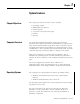
Chapter 1 System Features Chapter Objectives This chapter provides an overview of the computer. • • • • • • Computer Overview Operating systems Multilingual user interface Product options Accessories and replacement parts Features Parts list The VersaView Industrial Non-display Computers run factory operations from small visual interface and maintenance applications to large control and information applications.
System Features Computers with rotating-media hard drives include a recovery partition on the system drive containing the original factory image. You can use the supplied System Accessories/Cloning CD to restore the operating system from the recovery partition, create a new recovery image, and create bootable external recovery media. Refer to the Cloning Utility documentation, publication 6000-TD001, for instructions. You can view or download publications at http://literature.rockwellautomation.com.
System Features Product Options Cat. No. The table summarizes the product options available for the VersaView Industrial Non-display Computers.
System Features Features The illustrations show the features of each computer. VersaView 200R Computer The performance model is shown.
System Features 13 VersaView 700R Computer 2 1 3 4 5 6 7 8 11 9 10 Item Description Item Description 1 Floppy drive 7 Audio connector 2 CD drive 8 Ethernet port (RJ45) 3 Power switch 9 PS/2 keyboard or mouse port 4 Parallel printer port 10 Power input, ac 5 Serial COM ports, 2 11 USB port 6 VGA port Publication 6155R-UM001G-EN-P - July 2007
System Features VersaView 1400R Computer 1 2 3 4 5 6 7 11 8 10 9 Publication 6155R-UM001G-EN-P - July 2007 Item Description Item Description 1 Floppy drive 7 Audio connector 2 CD drive 8 Ethernet port (RJ45) 3 Power switch 9 PS/2 keyboard or mouse port 4 Parallel printer port 10 USB port 5 Serial COM ports, 2 11 Power input, ac 6 VGA port
System Features Before You Begin 15 Before unpacking the product, inspect the shipping carton for damage. If damage is visible, immediately contact the shipper and request assistance. Otherwise, proceed with unpacking. Keep the original packing material in case you need to return the product for repair or transport it to another location. Use both the inner and outer packing cartons to provide adequate protection for a unit returned for service.
System Features Publication 6155R-UM001G-EN-P - July 2007
Chapter 2 Installation Chapter Objectives This chapter shows how to install your computer on a machine, wall, DIN rail, or rack, and how to make computer connections. Review each mounting type and the product dimensions before installation. European Union Compliance This product meets the European Union Directive requirements when installed within the European Union or EEA regions and have the CE mark.
Installation Environment and Enclosure Information Review the information on enclosures and environments before installing the product. ATTENTION Environment and Enclosure This equipment is intended for use in a Pollution Degree 2 industrial environment, in overvoltage Category II applications (as defined in IEC publication 60664-1), at altitudes up to 2000 m (6561 ft) without derating. This equipment is considered Group 1, Class A industrial equipment according to IEC/CISPR Publication 11.
Installation Mounting Hardware The table lists the hardware required to mount each computer.
Installation Mount the Computer on a Machine You can mount the VersaView 200R and 700R computers on a shelf inside a machine by using mounting brackets. The brackets secure the computer to the shelf. 1. Attach the two mounting brackets to the bottom of the computer by using four of the provided screws. For the 200R computer, use four of the M3 x 5 mm panhead screws, and torque to 0.678 Nm (6 lb-in). 34.5 [1.36] VersaView 200R 92 [3.62] 2.
Installation 233.00 [9.17] 213.00 [8.39] 50.00 [1.97] 260.00 [10.24] 50.00 [1.97] 21 24.00 [0.94] VersaView 700R 3. Place the computer on the shelf and align the holes in the mounting brackets with the holes in the shelf. 4. Insert the remaining screws through the mounting bracket into the shelf and tighten. For the VersaView 200R computer, use four of the provided, M3 x 5 mm, panhead screws.
Installation Mount the Computer on a Wall You can mount the VersaView 200R computer on a wall inside a machine by using mounting brackets. The brackets secure the computer to the wall. 1. Attach the two mounting brackets to the rear of the computer by using four of the provided, M3 x 12 mm panhead screws; torque to 0.678 Nm (6 lb-in). 115.40 [4.54] 92.00 [3.62] 204.20 [8.04] 192.20 [7.57] 172.20 [6.78] 11.7 [4.61] 2.
Installation 23 Mount the Computer on a DIN Rail You can mount the VersaView 200R computer on a DIN rail. The DIN rail bracket mounts to the bottom or back of the computer. IMPORTANT Do not mount the computer on a DIN rail in high shock and vibration environments. 1. Fasten the DIN rail bracket on the bottom or back of the computer by using four, M3 x 5 mm panhead screws; torque to 0.678 Nm (6 lb-in). Rear Mount DIN Rail Bottom Mount DIN Rail Bottom Mount DIN Rail 74.58 [2.94] 74.58 [2.94] 152.
Installation Mount the Computer on a Rack You can install the VersaView 1400R computer in a rack cabinet that conforms to EIA standards for equipment with 483 mm (19 in.) wide panels. The cabinet must accommodate the computer’s height and depth, and also provide rear clearance for cables and air flow. A cabinet with a depth of 610 mm (24 in.) is sufficient. The computer must be supported by rack slides or fastened to a shelf.
Installation 25 VESA Mount the 200R Computer You can VESA mount the VersaView 200R computer to any of the VersaView industrial monitors or other surface by using the VESA mounting bracket provided. 1. Orient and attach the VESA mounting bracket to the four, 100 mm VESA holes that will be used to mount the computer. Use four, M4 x 8 mm flathead screws with four, M4 x 3 mm nuts. If attaching the bracket to the back of a VersaView monitor, the nuts are not needed. Dimensions are in mm (in.). 100 [3.
Installation The illustration shows the VersaView 200R computer VESA mounted to the back of a VersaView 1700M monitor.
Installation The illustrations show product dimensions in mm (in.). VersaView 200R Computer 150.00 [5.91] 115.40 [4.54] 172.20 [6.78] VersaView 700R Computer 431.30 [16.98] 253.00 [9.96] 192.00 [7.56] 258.00 [10.
Installation 560.00 [22.05] 517.00 [20.34] 508.00 [20.00] VersaView 1400R Computer 176.00 [6.93] 165.10 [6.50] 101.60 [4.00] 481.80 [18.97] 465.00 [18.31] 431.00 [16.97] Connect the Keyboard and Mouse You can plug either a keyboard or mouse into the PS/2 port on the computer. You can connect both devices by using the PS/2 adapter cable that is shipped with the computer.
Installation Connect Power 29 The power connection for the computers varies by model. • The VersaView 200R computer connects to either a 120/240V ac or 9…36V dc power source, depending on the model. • The VersaView 700R and 1400R computers connect to a 120/240V ac power source. Connect ac Power Computers with an ac power input use a standard IEC 320 power cord. The power supply input accepts 120/240V ac and is autoranging.
Installation Connect dc Power The power supply on the VersaView 200R computer has a dc input terminal block for connecting to a 9…36V dc power source. ATTENTION • Connect the dc ground connection to a power source with an earth ground to prevent electrical shock. Failure to follow this warning could result in electrical shock. • The computer circuit should have its own disconnect. Use an uninterruptible power source (UPS) to protect against unexpected power failure or power surges.
Installation Connect to Network 31 The computer connects to the Ethernet network by using CAT5 or CAT5E twisted-pair Ethernet cabling with RJ45 connectors. IMPORTANT To prevent performance degradation of Ethernet communication, do not subject the computer or cables to extreme radiated or conducted high-frequency noise. Proper cable routing and power conditioning is required for reliable Ethernet communication in industrial environments.
Installation Publication 6155R-UM001G-EN-P - July 2007
Chapter 3 Operation Chapter Objective This chapter covers these topics: • Operating guidelines • Starting the system • Resetting the system • Universal serial bus (USB) ports Operating Guidelines Observe these operating guidelines when using your computer: • If you are using an external monitor, turn the monitor on first. • Always use the proper power down procedures as required by your operating system, such as the Shut Down command in the Microsoft Windows operating system.
Operation Start the System Apply power to the computer. The computer performs a Power On Self Test (POST). The processor board, memory, keyboard, and certain peripheral devices are tested. Use a monitor if you want to view the progress of the POST and initialization of accessory devices. The monitor displays the startup dialogs for the operating system that is installed. If your system does not start, or you notice other anomalies, refer to the System Troubleshooting chapter.
Chapter 4 Replace System Components Chapter Objectives This chapter provides procedures to perform these tasks: • Remove the cover • Install add-in cards • Replace the hard disk drive • Connect an external drive • Replace memory modules • Load a memory card • Replace the battery • Replace the fan filter Accessories and Replacement Parts You can view a current list of accessories at the Rockwell Automation Allen-Bradley website http://www.ab.com/industrialcomputers.
Replace System Components Remove the Cover To install or upgrade computer components, you must first remove the cover. SHOCK HAZARD Failure to follow proper safety precautions could result in severe electrical shock and or damage to the computer. Required Tools You need a #2 Phillips screwdriver. Remove the Cover of the 200R Computer Follow these steps to remove the cover of the VersaView 200R computer. 1. Disconnect power from the computer. 2.
Replace System Components 37 Remove the Cover of the 700R Computer Follow these steps to remove the cover of the 700R computer. 1. Disconnect power from the computer. 2. Remove the three screws on each side. 3. Remove the top plate. Remove the Cover of the 1400R Computer Follow these steps to remove the cover of the 1400R computer. 1. Disconnect power from the computer. 2. Remove the three screws on each side. 3. Remove the top plate by moving it back, then up.
Replace System Components Install Add-in Cards You can install PCI or ISA add-in cards in the VersaView 700R and 1400R computers. SHOCK HAZARD ATTENTION Failure to follow proper safety precautions could result in severe electrical shock or damage to the computer. Add-in cards are sensitive to ESD and require careful handling. Hold cards only by the edges. Do not touch connectors, components, or circuits. After removing a card, place it on a flat, static-free surface, component side up.
Replace System Components 39 Install Add-in Cards in the 700R Computer Follow these steps to install add-in cards in the VersaView 700R computer. 1. Disconnect power from the computer. 2. Remove the top cover. 3. Remove the four screws in each hold-down bar. 4. Remove the hold-down bars. 5. Remove the screw and blank orb from the selected slot. 6. Gently, but firmly, install the add-in card into the appropriate expansion slot and screw in the orb. 7.
Replace System Components Install Add-in Cards in the 1400R Computer Follow these steps to install add-in cards in the VersaView 1400R computer. 1. Disconnect power from the computer. 2. Remove the top cover. 3. Remove the four screws on each hold-down bar. 4. Remove the hold-down bars. 5. Remove the screw and blank orb from the selected slot. 6. Gently, but firmly, install the add-in card into the appropriate expansion slot and screw in the orb. 7.
Replace System Components Replace the Hard Disk Drive 41 Follow these precautions when working with the hard disk drive: • Do not touch internal components. • Always handle the hard disk drive by its metal frame. • Store the hard disk drive in an anti-static bag when it is not installed. • Never remove or install a hard disk drive with the power on. SHOCK HAZARD ATTENTION ATTENTION Failure to follow proper safety precautions could result in severe electrical shock and/or damage to the computer.
Replace System Components Remove the Hard Disk Drive on the 200R Computer Follow these steps to remove the hard disk drive of the VersaView 200R computer. 1. Disconnect power from the computer. 2. Remove the four screws from the bottom of the enclosure that secure the hard disk drive assembly. 3. Pull the handle to slide the hard disk drive carrier out of the enclosure. 4. Remove the four screws that hold the hard disk drive to the bracket. 5. Lift the hard disk drive out of the carrier. 6.
Replace System Components 43 Install a Hard Disk Drive in the 200R Computer Follow these steps to install a hard disk drive in the VersaView 200R computer. 1. Connect the IDE ribbon cable to the hard disk drive. 2. Place the hard disk drive into the bracket and secure it by using the four screws; torque to 0.452 Nm (4 lb-in). 3. Gently slide the hard disk drive assembly into the bracket. 4. Secure the hard drive carrier by fastening the four screws to the bottom of the enclosure and torque to 0.
Replace System Components Connect an External Drive Observe these precautions when connecting an external drive: • Always handle the media by its case. • Avoid touching the cable connectors. • Remove disks before disconnecting power to the drive. • Do not expose the external drive to severe shock or temperature. • Operate the external drive only on a flat surface. • Do not move the external drive while it is operating. Sample External Drives Examples of external drives are listed. • Lacie 1.
Replace System Components Add or Remove Memory 45 The CPU board in the VersaView 700R and 1400R computers has two 168-pin sockets. Each socket supports a single or double-sided 3.3V dual in-line memory module (DIMM). Use the Allen-Bradley 512 MB DIMM (catalog number 6189V-DIMM512) for memory replacement or expansion. TIP We recommend that you use only qualified Allen-Bradley parts. Memory for the VersaView 200R computer is not serviceable or upgradeable.
Replace System Components Add or Remove Memory Modules Follow these steps to add or remove memory modules in a VersaView 700R or 1400R computer. 1. Disconnect power from the computer. 2. Remove the top cover. 3. Remove any retaining brackets blocking access to the memory module. The DIMM sockets are near the top of the CPU board. 4. Remove the existing memory modules from the CPU card by clipping the cable tie, and pressing outward on the retaining latches. 5.
Replace System Components Load a Memory Card 47 The VersaView 200R computer has a CompactFlash slot for loading memory cards. Follow these steps to load a card in the CompactFlash slot of a VersaView 200R computer. 1. Locate the CompactFlash slot on the front of the computer. 2. Remove the CompactFlash cover by removing the screw on each side of the cover. 3. Insert the card into the card slot until it is firmly seated. ATTENTION Do not force the card into the slot.
Replace System Components Replace the Battery The computers use nonvolatile memory that require a battery to retain system information when power is removed. The lithium battery is in a battery holder on the computer’s CPU board. • For the VersaView 700R and 1400R computer, replace this battery as needed with a Panasonic battery, part number CR2032, or equivalent. • For the VersaView 200R computer, replace the battery as needed with a specially-packaged replacement part from Allen-Bradley.
Replace System Components Replace the Fan Filter 49 Replace the fan filters every 6…12 months. The replacement schedule depends on the environment. The more severe the environment, the more often you need to replace the filter. The VersaView 200R computer is fanless and does not require replacement of the fan filters. To locate approved VersaView fan filters, go to the website http://www.ab.com/industrialcomputers.
Replace System Components Publication 6155R-UM001G-EN-P - July 2007
Chapter 5 System Troubleshooting Chapter Objectives This chapter provides information on troubleshooting anomalies with your computer. • • • • Troubleshooting Procedure Troubleshooting procedure Diagnostic utility Troubleshooting checklists Shipping information To identify and isolate an anomaly with your computer, follow these steps. 1. Shut down the computer’s operating system by using the appropriate method for your operating system. 2. Disconnect the power to the computer. 3.
System Troubleshooting 8. If the anomaly is not related specifically to a software installation or peripheral device, refer to the diagnostic utility and the troubleshooting checklists. Diagnostic Utility If you followed the troubleshooting procedure and are still having anomalies, use the VersaView diagnostic utility to isolate the anomaly. This utility determines the cause of the malfunction by testing computer components.
System Troubleshooting 53 • Are the memory modules fully installed? • Does your system have a computer virus? Run anti-virus software. • If there is a flickering display, unexpected restarts, or a locked system, exit the application and start over. Although the computers have a regulated and protected power supply, a transient voltage in the power line or peripheral cable could cause errors.
System Troubleshooting Problems With the Display • Are the display contrast and brightness controls properly adjusted? Refer to the operating system containing the video driver for setup functions. • Is the monitor compatible with the selected video mode? Press Auto Adjust on the monitor. • Is the monitor functioning properly? Verify monitor operation by connecting it to another computer. • Is the selected character color the same as the background color? If so, change the character color.
Appendix A Specifications VersaView Industrial Non-display Computers Attribute Value System Display description Processor type Standard models 200R 700R 1400R Performance models 200R 700R 1400R Expansion slot description 200R 700R 1400R RAM, 200R 6155R models Standard Performance RAM, 200R 6155F models Performance Intel Celeron M, 1 GHz Intel Pentium 4 Celeron, 2 GHz Intel Pentium 4 Celeron, 2 GHz Intel Celeron M, 1 GHz Intel Pentium 4, 2 GHz Intel Pentium 4, 2 GHz 1 CompactFlash slot Half-length: 3 P
Specifications Attribute I/O 200R standard 200R performance 700R, 1400R Operating system 200R 700R, 1400R Value 2 serial ports, 1 PS/2 port (keyboard/mouse), 1 Ethernet port 10/100 Mbps, VGA port, 4 USB 2.0 ports, audio line out port 2 serial ports, 1 PS/2 port (keyboard/mouse), 2 Ethernet ports 10/100 Mbps , 1 VGA port, 4 USB 2.0 ports, audio line out port 2 serial ports, 1 PS/2 port (keyboard/mouse), 1 parallel port, 1 Ethernet port 10/100 Mbps, 1 VGA port, 1 USB 1.
Specifications 57 Environmental Attribute Value Temperature, operating 0…50 °C (32…122 °F) Temperature, storage -20…60 °C (-4…140 °F) Relative humidity 10…90% noncondensing Shock, operating 15 g (1/2 sine, 11 ms) Shock, nonoperating 30 g (1/2 sine, 11 ms) Vibration, operating 200R 6155R rotating hard drive 6155F solid-state drive 700R and 1400R 1 Grms random 0.012 in. p-p, 10…57 Hz, 2 g peak, 57…500 Hz 0.006 in. p-p, 10…57 Hz, 1 g peak, 57…500 Hz Vibration, nonoperating 0.012 in.
Specifications Publication 6155R-UM001G-EN-P - July 2007
Appendix B Upgrade to a New BIOS Sometimes a new BIOS is released to enhance the performance of your computer, make it compatible with new hardware or software, or to correct a defect. You can download BIOS updates from the Rockwell Automation website http://www.ab.com/industrialcomputers to update your computer. Follow these steps to update the BIOS in your computer. 1. Attach a monitor and keyboard to your computer. For the 200R computer, connect an external USB floppy drive. 2.
Upgrade to a New BIOS Publication 6155R-UM001G-EN-P - July 2007
Index A add-in cards 38 700R 39 B battery replacement 48 BIOS upgrade 59 boot the system 34 mounting hardware 19 network connection 31 power connection 29 product dimensions 27 rack mounting 24 required tools 18 wall mounting 22 K keyboard and mouse connection 28 C catalog numbers 11 CompactFlash card 47 cover, remove 36 D dimensions 27 DIMM 45 DIN rail mounting 23 E electrostatic discharge caution 35 environment and enclosures 17 external drive 44 F fan filter replacement 49 features 1400R 14 200R 1
Index T troubleshooting anomaly running software 53 checklist 52 diagnostic utility 52 display 54 during startup 51, 52 external monitor 54 Publication 6155R-UM001G-EN-P - July 2007 U USB ports 34 W wall mounting 22
Rockwell Automation Support Rockwell Automation provides technical information on the Web to assist you in using its products. At http://support.rockwellautomation.com, you can find technical manuals, a knowledge base of FAQs, technical and application notes, sample code and links to software service packs, and a MySupport feature that you can customize to make the best use of these tools.