User Manual Compact Non-display Industrial Computers Catalog Numbers 6155F-NPXP, 6155F-NPXPDC, 6155F-NPWE, 6155F-NPWEDC, 6155R-NSXP, 6155R-NPXP, 6155R-NPXPDC
Important User Information Read this document and the documents listed in the additional resources section about installation, configuration, and operation of this equipment before you install, configure, operate, or maintain this product. Users are required to familiarize themselves with installation and wiring instructions in addition to requirements of all applicable codes, laws, and standards.
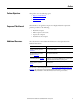
Summary of Changes This manual contains new and updated information. Changes throughout this revision are marked by change bars, as shown to the right of this paragraph. New and Updated Information This table contains the changes made to this revision.
Summary of Changes Notes: 4 Rockwell Automation Publication 6155R-UM002E-EN-P - February 2014
Table of Contents Preface Preface Objectives. . . . . . . . . . . . . . . . . . . . . . . . . . . . . . . . . . . . . . . . . . . . . . . . . . 7 Purpose of This Manual . . . . . . . . . . . . . . . . . . . . . . . . . . . . . . . . . . . . . . . . . . . . 7 Additional Resources . . . . . . . . . . . . . . . . . . . . . . . . . . . . . . . . . . . . . . . . . . . . . . . 7 Abbreviations. . . . . . . . . . . . . . . . . . . . . . . . . . . . . . . . . . . . . . . . . . . . . . . . . . . . . .
Table of Contents Chapter 4 Component Replacement Chapter Objectives . . . . . . . . . . . . . . . . . . . . . . . . . . . . . . . . . . . . . . . . . . . . . . . Accessories and Replacement Parts. . . . . . . . . . . . . . . . . . . . . . . . . . . . . . . . . Voltage Precautions . . . . . . . . . . . . . . . . . . . . . . . . . . . . . . . . . . . . . . . . . . . . . . Electrostatic Discharge Precautions . . . . . . . . . . . . . . . . . . . . . . . . . . . . . . . . Pre-configuration. . . . . . . . . .
Preface Preface Objectives This preface covers the following topics: • Purpose of This Manual • Additional Resources • Abbreviations Purpose of This Manual This manual is a user guide for compact non-display industrial computers. It provides procedures to the following: • • • • Additional Resources Install the computer. Make computer connections. Operate the computer. Troubleshoot the computer. These documents contain additional information to related products from Rockwell Automation.
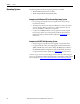
Preface Abbreviations 8 This publication can use the following abbreviations. Abbr Meaning Abbr Meaning ACPI Advanced configuration (and) power interface PCB Printed circuit board AHCI Advanced host controller interface PCDC Product Compatibility and Download Center AMI American Megatrends, Inc.
Chapter 1 Features Chapter Objectives This chapter provides information on the following topics: • Computer Overview • Operating Systems • Computer Options • Before You Begin • Parts List • Hardware Features Computer Overview Compact non-display industrial computers provide the functionality and performance needed to run visual interface, maintenance, and control applications. Combine the computer with any Allen-Bradley® industrial display to complete your system.
Chapter 1 Features Operating Systems The following Microsoft-licensed operating systems are available: • Windows XP Professional, Service Pack 3 • Windows Embedded Standard (WES) 2009 Computers with Windows XP Professional Operating System • No operating system updates have been applied to the factory image beyond Service Pack 3. • The I386 source directory for Microsoft Windows is on the system drive of your computer off the root directory, C:\I386.
Features Computer Options This table summarizes the options available for compact non-display industrial computers. A comparative summary of features for the computers is in Appendix A, Specifications on page 47. Cat. No.
Chapter 1 Features Hardware Features The illustration in this section shows the hardware features of the computer. The performance model is shown.
Chapter 2 Installation Chapter Objectives This chapter provides information on the following topics: • Installation Precautions • Installation Guidelines • Mounting Clearance Requirements • Computer Dimensions • Required Tools • Install the Computer • Connect Peripherals • Connect Power • Functional Ground Screw • Connect to a Network Review each mounting type and computer dimensions before installing.
Chapter 2 Installation Installation Precautions Read and follow these precautions before installing the computer. Environment and Enclosure Information ATTENTION: This equipment is intended for use in a Pollution Degree 2 industrial environment, in overvoltage Category II applications (as defined in IEC 60664-1), at altitudes up to 2000 m (6561 ft) without derating. This equipment is considered Group 1, Class A industrial equipment according to IEC/CISPR 11.
Installation Installation Guidelines Chapter 2 Follow these guidelines to make sure your computer provides safe and reliable service. • The installation site must have sufficient power. ATTENTION: To maintain an electrically safe installation, AC powered computers must be plugged into a grounded outlet. • In dry environments, static charges can build up easily. Proper grounding of the computer helps to reduce static discharges, which can cause shock and damage electronic components.
Chapter 2 Installation Computer Dimensions Review computer dimensions to estimate the clearance necessary for computer installation. Dimensions are given in mm (in.). Top View 158 (6.22) 115 (4.51) 172 (6.77) Front View Required Tools These tools are required for computer installation: • • • • Install the Computer 158 (6.
Installation Chapter 2 Mount the Computer on a Wall You can mount the computer on a wall by using a mounting bracket. See Figure 1 on page 20 for the wall mount bracket dimensions. Follow these steps to mount the computer on a wall. 1. Drill and tap four M4 holes in the wall (5 mm min) that correspond to the holes in the mounting bracket. 2. Attach the mounting bracket to the bottom or back of the computer (A). 3. Secure the mounting bracket by using four of the provided M4 x 8 mm panhead screws (B).
Chapter 2 Installation Mount the Computer on a DIN Rail You can mount the computer on a DIN rail by using a DIN-rail bracket that mounts to the back of the computer. See Figure 1 on page 20 for the DIN-rail bracket dimensions. IMPORTANT Do not mount the computer on a DIN rail in high shock and vibration environments. Follow these steps to mount the computer on a DIN rail. 1. Attach the DIN-rail bracket to back of the computer (A). 2.
Installation Chapter 2 VESA Mount the Computer You can mount the computer to any Allen-Bradley industrial display or other surface by using the provided VESA mounting bracket. This bracket is compliant with the VESA 100 x 100 mm mounting hole pattern. See Figure 1 on page 20 for the VESA mounting bracket dimensions.
Chapter 2 Installation Figure 1 - Mounting Bracket Dimensions Wall Mounting Bracket All dimensions are in mm (in.) 172 (6.77) 212 (8.346) 6 (0.236) 46 (1.811) 92 (3.622) 64 (2.52) 114.6 (4.512) 140 (5.511) 11.3 (0.444) 150 (5.90) 192 (7.56) DIN-rail Mounting Bracket 86 (3.385) 46 (1.811) 49 (1.929) 92 (3.622) 114 (4.488) 80 (3.149) 140 (5.511) 172 (6.771) 8.5 (0.334) 16 (0.629) VESA Mounting Bracket 2 (0.079) 100 (3.94) 84 (3.318) 156 (6.14) 100 (3.94) 176.4 (6.
Installation Connect Power Chapter 2 The computer connects to either a 100…240V AC or 9…36V DC power source, depending on the model. ATTENTION: When connecting power to the computer for the first time, the following actions occur: • The default BIOS setting automatically starts the computer after it is plugged into a power source. • You must read and accept an End User Setup procedure for computers with a Windows operating system (requires an external display).
Chapter 2 Installation 3. Connect the AC power cord to a power source. SHOCK HAZARD: Connect the AC power cord to a power source with an earth ground. Failure to follow this warning can result in electrical shock. 4. Apply 100…240V AC power to the computer. Connect DC Power Computers with a catalog number ending in DC have a DC input terminal block for connecting to a 9…36V DC power source. DC power models support operation from either a SELV or PELV power source.
Installation Functional Ground Screw Chapter 2 The pre-installed functional ground screw is not required for safety or regulatory compliance. However, if a supplemental ground is desired, use the functional ground screw below the power input. If using the functional ground screw, connect the computer to earth ground by using a 1.5 mm2 (16 AWG) or larger external wire. Use a ground wire with green insulation and a yellow stripe for easy identification.
Chapter 2 Installation Notes: 24 Rockwell Automation Publication 6155R-UM002E-EN-P - February 2014
Chapter 3 Operation Chapter Objectives This chapter provides information on the following topics: • Operating Guidelines • Start the Computer • Restart the Computer • Shut Down the Computer Operating Guidelines Follow these operating guidelines for your computer. • If you are using an external display, turn on the display first. • Do not operate the computer with the covers removed. Removing the covers disrupts air flow and results in overheating.
Chapter 3 Operation Start the Computer Follow these steps to start the computer. IMPORTANT The following steps apply to when you must manually start the computer. See Connect Power on page 21 for when power is applied to the computer for the first time. 1. Make sure any connected components with separate power supplies (such as an external display) are turned on first. 2. Make sure all necessary peripheral devices are connected to the corresponding I/O ports on the computer. 3.
Operation Restart the Computer Chapter 3 Use either of the following methods to restart your computer: • From the Start menu, choose Restart. • Press CTRL+ALT+DEL on an attached keyboard. During a restart, the computer does the following: • Clears the RAM. • Starts the POST. • Initializes peripheral devices such as drives and printers. • Loads the operating system.
Chapter 3 Operation Notes: 28 Rockwell Automation Publication 6155R-UM002E-EN-P - February 2014
Chapter 4 Component Replacement Chapter Objectives This chapter provides information on the following topics: • Accessories and Replacement Parts • Voltage Precautions • Electrostatic Discharge Precautions • Pre-configuration • Post-configuration • Required Tools • Remove the Bottom Plate • Reinstall the Bottom Plate • CompactFlash Card • Drive Precautions • Replace a Drive • Replace or Upgrade the Memory Module • Replace the RTC Battery Accessories and Replacement Parts You can view a list of accesso
Chapter 4 Component Replacement Electrostatic Discharge Precautions ATTENTION: Electrostatic discharge (ESD) can damage static-sensitive devices or microcircuitry. • Disconnect all power before working on the computer as detailed in Voltage Precautions on page 29. • Observe proper packaging and grounding techniques to prevent damage. Follow the precautions listed below. • Transport the computer and replacement parts in static-safe containers, such as conductive tubes, bags, or boxes.
Component Replacement Post-configuration Chapter 4 Follow these steps after installing or removing a hardware component. 1. Make sure all components are installed according to instructions. 2. Make sure that no tools or loose parts are left inside the computer. 3. Reinstall any expansion boards, peripherals, and system cables that were previously removed. 4. Reinstall the bottom plate according to the instructions on page 32. 5. Reconnect all external cables and power to the computer. 6.
Chapter 4 Component Replacement 5. Insert a slot-head screwdriver into the gap between the top and bottom plates and push the screwdriver to slide the bottom plate forward (C). 6. Detach the bottom plate from the computer (D). D C 7. After installing, replacing, or upgrading internal computer components, reinstall the cover as detailed in Reinstall the Bottom Plate on page 32. Reinstall the Bottom Plate Follow these steps to reinstall the bottom plate.
Component Replacement CompactFlash Card Chapter 4 The computers have one external and one internal CompactFlash (CF) Type II card slots for loading CF cards. Load a Card in the External CF Card Slot Follow these steps to load a card in the external CF card slot. IMPORTANT The external CF card slot is hot-swappable. You can insert or remove a card from this slot while the computer is on. 1. Remove the screw that secures the external CF card slot cover (A). 2. Remove the CF card slot cover (B). 3.
Chapter 4 Component Replacement 4. Insert the CF card into the slot and make sure it is properly seated. ATTENTION: When properly seated, more than 80% of the CF card easily inserts into the slot before you encounter resistance. If you encounter resistance before then, remove the card, rotate it 180°, and reinsert. Do not force the card into the slot. Forcing the card into the slot can damage the connector pins. 5. Reinstall the bottom plate as detailed in Reinstall the Bottom Plate on page 32. 6.
Component Replacement Replace a Drive Chapter 4 Follow these steps to replace a drive (HDD or SSD). 1. Read and follow the Drive Precautions on page 34. 2. Follow the steps for Pre-configuration on page 30. 3. Loosen the one captive thumbscrew that secures the drive assembly (A). 4. Pull the handle to slide the drive assembly out of the enclosure (B). B A 5. Remove the fours screws that secure the protective plate (C). 6. Remove the protective plate from the drive carrier (D). 7.
Chapter 4 Component Replacement 10. Hold the new drive (HDD or SSD) by its edge and remove it from its protective packaging. 11. Align the new drive on the carrier (G). 12. Connect the power and data cables to the new drive (F). 13. Secure the new drive to the carrier with the four screws (E). Torque the screws to 0.452 N•m (4 lb•in). 14. Place the protective plate on top of the new drive (D). 15. Secure the protective plate with the fours screws (C). 16.
Component Replacement Replace or Upgrade the Memory Module Chapter 4 The computer’s motherboard has one dual-channel DDR-II SO-DIMM slot that supports up to 2 GB maximum system memory. Memory Configuration Guidelines Follow these guidelines when replacing or upgrading memory to the computers. · Use only standard unbuffered memory modules that conform to both PC2-5300 and SPD compliance industry standards. · Use only DDR-II type memory modules. · Use only memory modules with gold-plated contacts.
Chapter 4 Component Replacement 3. Push out the latches on both sides of the SO-DIMM slot (A). 4. Tilt and gently pull the memory module upward to remove it from its slot (B). A B A 5. Place the memory module on a static-dissipating work surface or inside an antistatic bag. 6. Hold the new memory module by its edge and remove it from its protective packaging. 7. Orient the module so that the notch on its bottom edge aligns with the keyed surface of the SO-DIMM slot (C).
Component Replacement Replace the RTC Battery Chapter 4 The computers use nonvolatile memory that require a RTC battery to retain system information when power is removed. The battery is on the computer’s motherboard. The battery must be replaced during the life of the computer. The battery life depends on the amount of time the computer is on, or on-time. IMPORTANT On-time (hrs/wk) Expected Battery Life (yrs) 0 4 40 5.
Chapter 4 Component Replacement Follow these steps to replace the RTC battery. 1. Follow the steps for Pre-configuration on page 30. 2. Remove the bottom plate as detailed in Remove the Bottom Plate on page 31. 3. Remove the two screws from the battery bracket (A). 4. Remove the battery bracket (B). 5. Disconnect the battery cable from the motherboard (C). 6. Remove the existing battery (D). 7. Place the new battery on the motherboard (E). 8. Place the bracket over the new battery (F). 9.
Chapter 5 System Troubleshooting Chapter Objectives This chapter provides information on the following topics: • Hardware Monitoring • Troubleshooting • Troubleshooting Checklists • Diagnostic Utility • Load the System Defaults • Clear the CMOS • Ship or Transport the Computer Hardware Monitoring The built-in hardware monitor of the computer tracks the operating threshold levels of the voltage and temperature sensors. Follow these steps to determine whether an operating threshold has been reached. 1.
Chapter 5 System Troubleshooting Troubleshooting Follow these steps to identify and isolate an issue with the computer’s operation. 1. Shut down the computer by using the appropriate method for the installed operating system. See Shut Down the Computer on page 27 for more information. 2. Disconnect power to the computer. 3. Disconnect all peripheral devices from the computer. 4. If using a keyboard and mouse, verify that they are properly connected. 5.
System Troubleshooting Chapter 5 • Is the BIOS properly configured? You can restore the default BIOS settings by either of the following methods: – Load system defaults as detailed in Diagnostic Utility on page 44. – Use the CMOS jumper to reset the BIOS as detailed in Clear the CMOS on page 45. Issues after Startup • If an issue is intermittent, you can have a loose connection.
Chapter 5 System Troubleshooting Issues with an External Display • Are the display contrast and brightness controls properly adjusted? Refer to the operating system containing the video driver for set-up functions. • Verify that the selected character color is not the same as the background color.
System Troubleshooting Load the System Defaults Chapter 5 If the computer fails after you make changes in the set-up menus, load the system default settings to correct the error. These default settings have been selected to optimize your computer’s performance. Follow these steps to load the system defaults. 1. Restart the computer as specified in Restart the Computer on page 33. 2. During POST, press F2 to access the BIOS set-up utility.
Chapter 5 System Troubleshooting 6. Place the jumper block over pins 2 and 3 for 10 seconds. 7. Return the jumper block to its default position. IMPORTANT The jumper block must be returned to its default position over pins 1 and 2. The computer does not start if you leave the jumper block over pins 2 and 3. 8. Reinstall the bottom plate as detailed in Reinstall the Bottom Plate on page 32. 9. Follow the steps for Post-configuration on page 31.
Appendix A Specifications The following tables contain specifications for the 200R compact non-display computers. For additional specifications, go to http://ab.rockwellautomation.com/Computers.
Appendix A Specifications Table 4 - Environmental Specifications Attribute 6155F-NPXP, 6155F-NPXPDC, 6155F-NPWE, 6155F-NPWEDC, 6155R-NSXP, 6155R-NPXP, 6155R-NPXPDC Dimensions (HxWxD), approx 115 x 172 x 158 mm (4.51 x 6.77 x 6.22 in.
Appendix B Upgrade to a New BIOS BIOS Upgrade Procedure Sometimes a new BIOS is released to enhance the performance of your computer or to correct a defect. In such cases, you can download BIOS upgrades at the Rockwell Automation Product Compatibility and Download Center (PCDC) website at http://www.rockwellautomation.com/support/pcdc. CD and floppy disk drive upgrades are available.
Appendix B Upgrade to a New BIOS 7. After the download completes, click Open to access the folder where ZIP files were downloaded. 8. Open the downloaded file to locate and extract the ISO (*.iso) file. 9. Write the ISO file to a blank CD/CD-RW with the included CD Write utility (or one of your choice). 10. With the BIOS upgrade CD in the CD drive, restart the computer. 11. During POST, press F2 to access the BIOS set-up utility.
Upgrade to a New BIOS Upgrade the BIOS from an External Floppy Disk Drive Appendix B Follow these steps to upgrade the BIOS in your computer from an external floppy disk drive. 1. Attach the following external peripherals to your computer: • Display • Keyboard • Floppy disk drive 2. Follow step 2 through step 7 in Upgrade the BIOS from an External CD Drive starting on page 49 before proceeding to step 3 in this section. 3. Open the downloaded file to locate and extract the executable (*.exe) file. 4.
Appendix B Upgrade to a New BIOS Notes: 52 Rockwell Automation Publication 6155R-UM002E-EN-P - February 2014
Index A accessories 29 B M memory DIMM slots 37 replace 37 BIOS upgrade 49 C catalog numbers 12 CMOS clear 45 CompactFlash card 33 component replacement memory 37 N network connection 23 LAN cable reminder 14 O operating the computer 25 overview 9 P D dimensions 16 DIN rail mounting 18 E environment and enclosures 13 environmental requirements considerations 15 parts list 11 POST, see Power On Self Test power indicator 12 power connection 21 AC power 21 notices 21 Power On Self Test product optio
Index T troubleshooting anomaly running software 43 checklist 42 clearing CMOS 45 load system defaults 45 problem analysis 42 54 V ventilation 15 VESA mounting 19 W Windows Operating Systems 10 Rockwell Automation Publication 6155R-UM002E-EN-P - February 2014
Rockwell Automation Support Rockwell Automation provides technical information on the Web to assist you in using its products. At http://www.rockwellautomation.com/support you can find technical and application notes, sample code, and links to software service packs. You can also visit our Support Center at https://rockwellautomation.custhelp.com/ for software updates, support chats and forums, technical information, FAQs, and to sign up for product notification updates.