
User Manual


Bulletin 6153 and 6154 Industrial Computers with Integrated CRT 21
Publication 6153-2.0
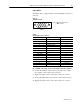
Video Cables
The HD15 cable is equipped with a conventional HD15 connector at
each end.
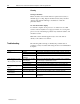
Figure 13
Standard VGA Cable
1234
5
678910
11 12
13
14 15
HD15
View looking into the Pin End of the
Male connector
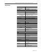
Table A
Standard Video Cable Construction
Monitor HD15 Signal Description Computer HD15
2 Green Video 2
7 Green Video Ground 7
1 Red Video 1
6 Red Video Ground 6
3 Blue Video 3
8 Blue Video Ground 8
5 Composite Sync 5 (Not Used)
11 (Floating) ID0 11
12 (Floating) ID1 12
4 (Gnd) ID2 4
9 Not Connected 9
14 Vertical Sync 14
10 Sync Ground 10
15 Control 15 (Not Used)
13 Horizontal Sync 13
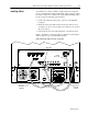
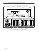
To establish connections between the monitor and the computer:
1. Connect the standard 15-pin connector end of the video cable to
the computer’s video cable’s VGA connector.
2. Tighten the captive screws on the cable connector to secure it.
3. Connect the VGA cable to the connector on the monitor section.
4. Tighten the captive screws on the cable connector to secure it.