Industrial Computers (Bulletin 6153, 6154) Product Data & Installation Instructions
Table of Contents ) (!'*!&%) "!% !)* .
Bulletin 6153 and 6154 Industrial Computers with Integrated CRT Descriptions The Allen-Bradley Bulletin 6153 and 6154 Industrial Computers feature: • integrated 20” color CRT monitor designed for industrial use • panel (Bulletin 6153) or rack (Bulletin 6154) mounting • 4-slot or 12-slot passive backplane or 8-slot active motherboard • your choice of CPU • many options for enhancement and expansion. Packing List Note: Check your shipment against the packing list in the shipping carton.
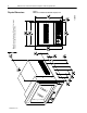
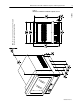
Bulletin 6153 and 6154 Industrial Computers with Integrated CRT Note: Be sure to allow at least 76.2 mm (3.00 in.) depth clearance for cable connections and air flow. Physical Dimensions Publication 6153-2.0 Figure 1 Dimensions of Bulletin 6153 Industrial Computer, 4 slot.
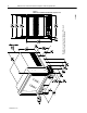
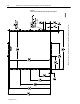
Bulletin 6153 and 6154 Industrial Computers with Integrated CRT 5 Note: Be sure to allow at least 76.2 mm (3.00 in.) depth clearance for cable connections and air flow. 130303 Figure 2 Dimensions of Bulletin 6153 Industrial Computer, 8/12 slot. Publication 6153-2.
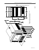
Bulletin 6153 and 6154 Industrial Computers with Integrated CRT 130301 Figure 3 Dimensions of Bulletin 6154 Industrial Computer, 4 slot. Note: Be sure to allow at least 76.2 mm (3.00 in.) depth clearance for cable connections and air flow. 6 Publication 6153-2.
Bulletin 6153 and 6154 Industrial Computers with Integrated CRT 7 Note: Be sure to allow at least 76.2 mm (3.00 in.) depth clearance for cable connections and air flow. 130304 Figure 4 Dimensions of Bulletin 6154 Industrial Computer, 8/12 slot. Publication 6153-2.
Bulletin 6153 and 6154 Industrial Computers with Integrated CRT Installation Instructions Environmental Considerations For proper cooling, the computer requires a minimum free air space of 7.6 cm. (3 in.) behind, 5.1 cm. (2 in.) above and below, and 2.5 cm. (1 in.) on the sides of the chassis. The computer is equipped with fans to help ensure proper cooling. Strong magnetic fields near the front of the computer outside the enclosure could potentially distort the image over time.
Bulletin 6153 and 6154 Industrial Computers with Integrated CRT 9 5. Remove the external bezel. 6. Insert the computer in the panel cutout from the front of the panel. 7. Place the washers (one of each) on the bolts provided and install through the front panel. 8. Secure with the included lock nuts, tightening them evenly to 25 inch pounds torque.
Bulletin 6153 and 6154 Industrial Computers with Integrated CRT Publication 6153-2.0 Note: Use the pairs of holes when mounting the Industrial Computer using rack slides.
Bulletin 6153 and 6154 Industrial Computers with Integrated CRT 11 130302 Note: Use the pairs of holes when mounting the Industrial Computer using rack slides. See Note Figure 6 Panel Cutout for Bulletin 6153 8/12-slot Industrial Computer Publication 6153-2.
Bulletin 6153 and 6154 Industrial Computers with Integrated CRT Rack Mounting, Bulletin 6154 The 6154 Industrial Computer can be installed in a rack cabinet that conforms to EIA standards for equipment with 19” wide panels. The cabinet must be tall enough to accommodate the computer’s height and deep enough to accommodate the unit’s depth, while providing rear clearance for cabling and air flow. A cabinet with a depth of 61 cm. (24 in.) is sufficient.
Bulletin 6153 and 6154 Industrial Computers with Integrated CRT 13 Connecting AC Power The computer requires a single phase power supply providing 90-132V AC or 180-264V AC at 47 to 63 Hz. Power must be available at the three-pin AC input receptacle situated in the rear of the unit. To connect AC power to the computer. 1. Turn off the mains switch or breaker. 2. Use the GND point on the rear panel of the monitor to establish a chassis to earth ground connection.
Bulletin 6153 and 6154 Industrial Computers with Integrated CRT Controls & Indicators The following is a summary of the controls and indicators on the Bulletin 6153 and 6154 Industrial Computer. Refer to figures 7 through 10 for help in locating specific controls or indicators.
Bulletin 6153 and 6154 Industrial Computers with Integrated CRT 15 Figure 8 Front Controls – 8/12-Slot Units CONTRAST DEGAUSS KBO RESET 0 1 POWER 180600 Bulletin 6153 8/12 Slot CONTRAST DEGAUSS KBO RESET 0 1 POWER Bulletin 6154 8/12-Slot 180597 Power Indicator The presence of AC power at the Bulletin 6153 or 6154 Industrial Computer is indicated by a green LED in the front panel. Publication 6153-2.
Bulletin 6153 and 6154 Industrial Computers with Integrated CRT Contrast and Brightness Controls The Bulletin 6153 and 6154 Industrial Computers are equipped with adjustable contrast and brightness controls. The 4-slot units have duplicate controls on the front and the back of the unit. The 8/12-slot units have a contrast control on the front, and both contrast and brightness controls on the back.
Bulletin 6153 and 6154 Industrial Computers with Integrated CRT 17 Degauss The monitor is equipped with an automatic degaussing system to remove residual magnetism from the CRT’s shadow mask at power-up. Degaussing helps keep the screen free of any color impurities which might otherwise result from magnetism picked up by the shadow mask from the earth’s magnetic field when the monitor is moved. In addition, two manual degauss push button are provided.
Bulletin 6153 and 6154 Industrial Computers with Integrated CRT Figure 10 Rear Panel Controls – 8/12-Slot Units Factory Adjustments Vertical Position Horizontal Size Horizontal Position – + – + – + – + AUX 2 DG VGA Raster Rotation Degauss Brightness Contrast Vertical Size Note: The internal degauss will not prevent color impurities caused by local magnetic fields. Make certain the Industrial Computer’s enclosure is free of residual magnetism.
Bulletin 6153 and 6154 Industrial Computers with Integrated CRT Installing Cables 19 You will need to connect a number of cables at the rear of the unit before your Industrial Computer will function. This section describes the cable connections you will need to make. While installing cables, be sure to keep the following points in mind. • Connect the cables according to the options in your Industrial Computer. • Route and secure the cables.
Bulletin 6153 and 6154 Industrial Computers with Integrated CRT Figure 12 Rear Panel Cable Connections – 8/12-Slot Units Video Cable – Touchscreen Serial Cable (Optional) + – + – + – + AUX 2 DG VGA Monitor Power Cord Publication 6153-2.
Bulletin 6153 and 6154 Industrial Computers with Integrated CRT 21 Video Cables The HD15 cable is equipped with a conventional HD15 connector at each end.
Bulletin 6153 and 6154 Industrial Computers with Integrated CRT Touchscreen, mouse and other input device setup To set up the front panel keyboard To enable the front panel keyboard connector, use a 5-pin DIN keyboard cable (4- or 12-slot units) or a PS2 keyboard cable (8-slot units) at the rear of the unit. Connect the male cable end to the computer’s Keyboard connector. An IBM AT keyboard may be connected to either the front panel 5-pin DIN connector or to the rear panel Keyboard connector.
Bulletin 6153 and 6154 Industrial Computers with Integrated CRT 23 To open the computer chassis You may have to open the computer chassis to install a card or for some other reason. 1. Disconnect and remove cables from the computer chassis. 2. Remove the two or three Phillips-head screws at the rear of the unit. 3. Slide the chassis straight back and out, taking care to support the chassis as it slides free. 4.
Bulletin 6153 and 6154 Industrial Computers with Integrated CRT Cleaning To inspect the filter Filters should be removed and cleaned or replaced as necessary to maintain proper cooling. Inspect the filter at least yearly, and more often in environments with large concentrations of airborne particulate matter. To clean the monitor display To clean the computer screen protector or touchscreen, use a 50% solution of alcohol (ethanol or isopropyl) in water on a cotton gauze pad or soft cotton cloth.
Bulletin 6153 and 6154 Industrial Computers with Integrated CRT 25 Specifications Processor/Memory Processor/Speed (MHz) 486DX4/100 MHz, Pentium/100 MHz, Pentium/166 MHz Memory Options 4M (for 486DX4/100 only), 8M, 16M, 32M, 64M System System Bus Architecture 16-bit ISA, 8 slots (active motherboard) 16-bit ISA, 4 or 12 slots (passive backplane) Available Expansion Slots: Active Motherboard Passive Backplane 4 full-length ISA, 3 PCI, 1 shared 2 full-length ISA (4 slot) or 10 full length ISA (12 slot
Bulletin 6153 and 6154 Industrial Computers with Integrated CRT Environmental (specifications assume standard configuration, excluding diskette drive) Temperature Operating +5°C to +45°C Storage -30°C to 60°C Relative Humidity 8% to 80% non-condensing Altitude Operating 0 to 10,000 ft. (3,000 m) Non-Operating 0 to 40,000 ft. (12,000 m) Vibration Operating 0.1in. p-p, 5-14 Hz sine; 1.0g peak, 14-500 Hz sine Non-Operating 0.2in. p-p, 5-14 Hz sine; 2.
Bulletin 6153 and 6154 Industrial Computers with Integrated CRT 27 Notes Publication 6153-2.
IBM is a registered trademark of International Business Machines Corporation VGA and PC AT are trademarks of International Business Machines Corporation. Pentium is a trademark of Intel Corporation Microsoft and Microsoft Windows are registered trademarks of Microsoft. Allen-Bradley, a Rockwell Automation Business, has been helping its customers improve productivity and quality for more than 90 years. We design, manufacture and support a broad range of automation products worldwide.