
Manual

Chapter 3
Installation
3-5
The procedure of installing the scanner board in the host has three main
steps:
1. Set the scanner board switch block for the memory address you
selected earlier.
2. Plug the scanner into a slot in the host computer.
3. Connect the I/O cable to the scanner.
In this section we’ll look at those steps in detail.
Switch Settings
The scanner board has one block of ten DIP switches to be set at
installation time.
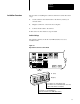
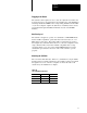
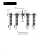
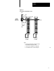
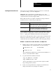
Figure 3.2
Dip
Switch Location on Scanner Board
Switches
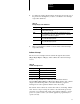
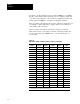
Set switches 1-6 set for RAM address.
(photo shows switches set for PC/AT)
(photo shows switches set for RAM address C4000)
off
on
(Close)
(Open)
Set switches 710 open for PC/XT (6120)
Set switches 710 closed for PC/AT (T50, 6121, 6122)
Installation
Procedure