IBM PC I/O Scanner (Cat. No.
Important User Information Because of the variety of uses for the products described in this publication, those responsible for the application and use of this control equipment must satisfy themselves that all necessary steps have been taken to assure that each application and use meets all performance and safety requirements, including any applicable laws, regulations, codes and standards. The illustrations, charts, sample programs and layout examples shown in this guide are intended solely for example.
Preface Summary of Changes Changes to Software Use this document with revision 1.2 of the host software package for the IBM PC I/O Scanner. The host software has been updated to use Microsoft and Borland compilers. The new information is marked with a vertical black bar in the margin.
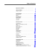
Table of Contents Important User Information . . . . . . . . . . . . . . . . . . . . . . . . I Summary of Changes . . . . . . . . . . . . . . . . . . . . . . . . . . . . i Changes to Software . . . . . . . . . . . . . . . . . . . . . . . . . . . . . . . . . i Using This Manual . . . . . . . . . . . . . . . . . . . . . . . . . . . . . . . 1 1 Manual's Objectives . . . . . . . . . . . . . . . . . . . . . . . . . . . . . . . . . . Audience . . . . . . . . . . . . . . . . . . . . . . . . . . . . . . .
ii Table of Contents Compiling and Linking the Microsoft C 5.1 or 6.0 Version . . . . . . . . Further Information . . . . . . . . . . . . . . . . . . . . . . . . . . . . . . . . . . . 4 14 4 15 Startup, Status, and Shutdown . . . . . . . . . . . . . . . . . . . . . 5 1 Chapter Objectives . . . . . . . . . . . . . . . . . . . . . . . . . . . . . . . . . . . Overview . . . . . . . . . . . . . . . . . . . . . . . . . . . . . . . . . . . . . . . . . . Startup . . . . . . . . . . . . . . . . . . . . . . .
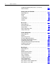
Table of Contents iii General Support Features . . . . . . . . . . . . . . . . . . . . . . . . . 9 1 Chapter Objectives . . . . . . . . . . . . . . . . . . . . . . . . . . . . . . . . . . . Timing Loops . . . . . . . . . . . . . . . . . . . . . . . . . . . . . . . . . . . . . . . Date and Time Stamp . . . . . . . . . . . . . . . . . . . . . . . . . . . . . . . . . Command Translation . . . . . . . . . . . . . . . . . . . . . . . . . . . . . . . . 9 1 9 1 9 3 9 5 User Diagnostic Program . . . . . . . .
Chapter 1 Using This Manual Manual's Objectives This manual describes the operation and use of the IBM PC I/O Scanner (cat. no. 6008-SI) with the supplied host software driver. After reading this manual, you should be able to: install the scanner board in your computer write a program that runs on your computer to control the scanner for your application diagnose and correct most of the problems that might occur.
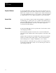
Chapter 1 Using This Manual Required Software You need the MS–DOS operating system, version 3.0 or higher. If you’re using the Microsoft C version of the scanner driver software, you’ll need a Microsoft C compiler, version 5.1 or higher (version 6.0 recommended). If you’re using the Borland C version of our software, you’ll need a Borland C compiler, Turbo C++ 1.0 or higher (Borland C++ 2.0 recommended).
Chapter 2 I/O Scanner Concepts Chapter Objectives This chapter explains basic concepts and provides an overview of the operation of the IBM PC I/O Scanner.
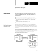
Chapter 2 I/O Scanner Concepts I/O modules sit in one or more chassis. An I/O chassis is a housing that holds one adapter and 1, 2, 4, 8, 12, or 16 I/O modules. The adapter is the communication interface between the scanner and the chassis. The scanner communicates with the adapter through shielded two–conductor twisted–pair cable (the “blue hose”). In turn, the adapter monitors and controls the I/O modules through the backplane of the chassis.
Chapter 2 I/O Scanner Concepts We can divide I/O, and therefore I/O modules, into discrete and intelligent modules. Discrete I/O is characterized by one terminal (or point) per I/O image table bit. Your program handles discrete I/O through I/O image tables, where each input or output terminal corresponds to one of the 1024 input and 1024 output image table bits (64 x 16 bits = 1024 bits.) The input image table is an area of memory that monitors the terminals of discrete input modules.
Chapter 2 I/O Scanner Concepts Quad density module: Discrete I/O module having 32 input or output points. I/O chassis: One of four different housings sized to hold either four, eight, twelve, or sixteen discrete I/O modules. Slot: Position in an I/O chassis the width of one discrete I/O module. I/O group: An addressing concept representing 16 input bits (one input image table word) and 16 output bits (one output image table word). In hardware, an I/O group can represent one or two slots in an I/O chassis.
Chapter 2 I/O Scanner Concepts Fault dependent group: A group of I/O adapters treated as a single entity for the purposes of fault detection. If one of the defined group faults all in the group are in fault. I/O Addressing You assign each adapter an I/O rack number (0 to 7) by setting switches on the adapter. A rack may be single chassis; or two to four chassis may be comprised in one rack number; or a single chassis can be addressed as two racks.
Chapter 2 I/O Scanner Concepts A slot is a position in an I/O chassis for one I/O module. In one–slot or single–slot addressing, an I/O group represents a single slot. In two–slot or double–slot addressing, an I/O group represents two slots. What the Scanner Does The scanner runs asynchronously in relation to the host. When either one wants to get the other’s attention, it must issue a hardware interrupt. Information is passed through a global RAM.
Chapter 2 I/O Scanner Concepts Thus you can be certain that the I/O image tables are refreshed once per scan list. Partial refreshes take place more frequently if your program executes a lot of block transfers or management requests: whenever the global ram is transferred the I/O image tables are refreshed as far as the scanner has got in the scan list since the last interrupt. Your program can also force a partial refresh: see the update function in chapter 6, Discrete I/O.
Chapter 2 I/O Scanner Concepts Because our interrupt handler takes care of all details of the global RAM, you don’t have to be concerned with the bits and bytes. You should know that the global RAM contains two kinds of information: the I/O image tables are comprised of an output image image table and an input image table.
Chapter 2 I/O Scanner Concepts The discrete output module turns on the output. Any external device attached to the output module then activates. For timing information, please see Timing of Discrete I/O in chapter 6, Discrete I/O. Scanner Commands There are two types of scanner commands, block transfers and management requests. There are two block transfer commands (BT commands): block transfer read block transfer write A management request affects the operation of the scanner itself.
Chapter 2 I/O Scanner Concepts Host Watchdog Suppose that your program crashes, either because of logic errors or because of operator intervention. Or suppose that through logic errors your program gets into an infinite loop. In these cases the program is no longer sending meaningful information to the scanner through the interrupt handler.
Chapter 3 Installation Chapter Objectives This chapter explains how to install the IBM PC I/O Scanner. After reading this chapter you should be able to: determine whether you already have hardware or software products installed that would conflict with the scanner configure the scanner board for a suitable address in your host’s RAM install the scanner board in the host connect the 1771 Series I/O cable to the scanner.
Chapter 3 Installation IBM’s Technical Reference Manuals show line IRQ3 used by the secondary serial port (COM2 device). If you have 2 serial ports active on your host computer and you have selected IRQ3, you must disable COM2 before installing the scanner board. (Many multi-junction cards have jumpers to disable this port; see your manufacturer’s documentation for details.
Chapter 3 Installation 5. To change the setting, pull the jumper off the pins and reposition it on the pins for the interrupt line you desire. See Table 3.A for interrupt request line definitions. Table 3.A Interrupt Request Line Definitions 6. Interrupt Line: Explanation: IRQ3 Default setting. Conflicts with COM2 port on machines so equipped. Conflicts with the KTP card. IRQ5 This setting conflicts with the hard disk controller when the card is used in an IBM XT or AT clone.
Chapter 3 Installation Despite IBM recommendations to the contrary, some resident software uses the system timer hardware interrupt, number 8, rather than the follow-on described in the preceding paragraph. The scanner may work erratically or may fail to work at all if such programs are active when a scanner program is started. I/O Ports The scanner does not use any I/O ports.
Chapter 3 Installation Installation Procedure The procedure of installing the scanner board in the host has three main steps: 1. Set the scanner board switch block for the memory address you selected earlier. 2. Plug the scanner into a slot in the host computer. 3. Connect the I/O cable to the scanner. In this section we’ll look at those steps in detail. Switch Settings The scanner board has one block of ten DIP switches to be set at installation time. Figure 3.
Chapter 3 Installation The factory sets the switches for memory address C000(hex) for an IBM PC AT or other machine with a 16-bit bus. If you’re running on a PC XT or another 8-bit bus machine, or if you want to configure the scanner at an address other than C000(hex), you’ll have to change the switches. First set switches 7 through 10 to all closed for a PC AT or similar, all open for a PC XT or similar. The factory setting is all closed, for a PC AT or other machine with a 16-bit bus.
Chapter 3 Installation Plugging in the Board The scanner board requires two slots. (Any two adjacent slots will do: the board doesn’t have to be plugged into any particular slot.) The Installation and Setup manual from IBM, or the corresponding manual from the maker of your host computer, explains in detail how to install any add-on board. (See the Internal Option Installation Instructions section in the IBM manual.) Host Bus Speed The scanner is designed to operate on a standard 6 to 8 Mhz IBM AT bus.
Chapter 3 Installation Figure 3.
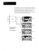
Chapter 3 Installation Figure 3.4 Connecting 1771 I/O Cable in Series Pin 1 Blue White Shield D-shell Connector (back view) Twin axial Cable Blue White Twin axial Cable Pin 8 Swing-Arm 1771-WB Swing-Arm 1771-WB Note: • Use the setup command to disconnect the shunt line termination resistor in the scanner. • You can connect a maximum of 16 swing arms. • Use termination resistor on the last swing arm.
Chapter 4 Programming Overview Chapter Objectives This chapter gives you a general overview of the programming process.
Chapter 4 Programming Overview Table 4.B lists the rest of the files that make up the source code for the user diagnostic program: Table 4.B Source Code for the User Diagnostic Program File: Contents: U_D1.C main program U_D1.H include file for the U_*.C files U_BT.C single block transfers U_BTC.C continuous block transfers U_BTM.C multiple block transfers U_DISC.C full screen discrete I/O U_GET.C keyboard handler U_GROUP.C single group discrete I/O U_MR.C management requests U_PICK.
Chapter 4 Programming Overview Installing the Borland Version This section provides installation suggestions. Feel free to modify this procedure according to your own configuration. Important: We recommend that you make backup copies of the distribution disks and keep the originals in a safe place, away from your computer and away from stray magnetic fields. Please make sure that your compiler is installed according to Borland’s instructions before you follow the procedure below. If you have a: Then: 3.
Chapter 4 Programming Overview 4. Create an EXAMPLES directory under your development directory, using this command: md examples 5. Copy the user diagnostic program (source code and executable) to this directory by typing the commands copy a:u*.? c:examples copy a:u_d1b.exe c:examples\u_d1.exe If you wish, you can print the source files (approximately 35 pages) by using this command: print examples\u_*.? Method 2: Scanner files in development directory 1.
Chapter 4 Programming Overview Installing the Microsoft Version This section provides installation suggestions. Feel free to modify this procedure according to your own configuration. We recommend that you make backup copies of the distribution disks and keep the originals in a safe place, away from your computer and away from stray magnetic fields. Please make sure that your compiler is installed according to Microsoft’s instructions before you follow the procedure below. If you have a: Then: 3.
Chapter 4 Programming Overview 4. Create an EXAMPLES directory under your development directory, using this command: md examples 5. Copy the user diagnostic program (source code and executable) to this directory by typing these commands: copy a:u*.? c:examples copy a:u_d1m.exe c:examples\u_d1.exe If you wish, you can print the source files (approximately 35 pages) by using this command: print examples\u_*.? Method 2: Scanner files in development directory 1.
Chapter 4 Programming Overview Writing Your Program In chapters 5 through 9, we’ll explain the details of writing application programs to communicate with the scanner. But first we’ll give you a bird’s-eye view. Header Files Every source program must contain these two lines: #include #include STDIO.H is the standard header file supplied with your compiler. H_6008SI.H is supplied on your scanner driver disk and defines constants, variables, and functions that your program needs.
Chapter 4 Programming Overview Here’s a sample program skeleton: #include #include void main(argc, argv) int argc; char *argv[ { ]; QMR pkt; . . . status = setup_6008(1, 1, 3, 0, &pkt); if ( status != OK ) { printf(“setup failed: command=%s status=%s\n”, xlat_cmd(status), xlat_conf(pkt.qmr_stat)); if ( status != C_AUTOCONF && status != C_SETUP ) printf(“scanner fatal error %d\n”, fatal_6008( )); abort( ); } . . . /* application logic here, including calls to host_active( ) */ . . .
Chapter 4 Programming Overview Defined Constants In their appropriate places in this manual we’ll tell you about various constants defined in the header file H_6008SI.H. There are three constants that are not used by our routines but are defined for your convenience, and we’ll list them now: MAXGROUP is the maximum number of module groups, 64. Groups in the I/O image tables are therefore numbered from 0 to MAXGROUP-1. MAXMOD is the maximum number of modules or slots, 132.
Chapter 4 Programming Overview The main program displays identification on the screen and then calls options (in the same source file) to read and interpret command line options. Next the main program calls init (also in the U_D1.C source file). In turn, init calls setup_6008 and checks for status. If the setup was unsuccessful, init displays a message and abort execution rather than returning to main. If setup succeeded, init returns control to main.
Chapter 4 Programming Overview File H_6008SI.H defines constants according to a logical pattern.
Chapter 4 Programming Overview Names of global variables in our libraries begin with g_. In addition, the libraries contain a number of undocumented internal global variables whose names begin with _q. In summary, you can create conflicts with names in our libraries by naming functions and extern variables beginning with g_, _q, io_, or IO_. To be safe, stay away from those names and from the names of functions documented in this manual. Compiling and Linking the Borland C++ 2.
Chapter 4 Programming Overview For information on selecting or excluding the 8087 or 80287 math coprocessor, please see the Borland manual sections on the –f options. Our libraries are compatible with any –f option because they contain no floating-point operations. Example 1: Your program is called APPLIC.C. You have selected the small (s) memory model. The combined command to compile and link would be BCC –N –K –w –ms –lcd applic.c 6008sisb.lib Borland C++ will compile applic.c as applic.
Chapter 4 Programming Overview Compiling and Linking the Microsoft C 5.1 or 6.0 Version These notes present a simple way of compiling and linking your application program with the scanner code. This way may or may not be the best way for your development. There are many alternatives – Microsoft’s Programmer’s Workbench, make files, and so on. You should evaluate the alternatives and decide which way is most productive for you.
Chapter 4 Programming Overview Example 2: If your program is in several source modules, you can list them on the command line. If you have chosen medium model, the command is CL /J /AM /W3 applic.c /link 6008simm The three source files will be compiled and linked as CONTROL.EXE. Example 3: You have many source files –– U_D1.C, U_BT.C, and so on –– to be compiled and linked in a program called U_D1M.EXE. Header files are not in the same directory as source code, but are in directory c:\dev\hdr.
Chapter 4 Programming Overview The last two chapters are concerned with diagnostics: Chapter 10, User Diagnostic Program, tells you how to use the diagnostic program that we included on your distribution disks. Chapter 11, Troubleshooting, has some questions and answers to help you in diagnosing problems.
Chapter 5 Startup, Status, and Shutdown Chapter Objectives This chapter explains features that must be in every scanner program. After reading this chapter, you should be able to write code that: tells the scanner to start operation lets the scanner know that your program is still active (the host watchdog) makes sure that the scanner is still active checks the current operating status of the scanner shuts down scanner operation in a way that leaves the scanner ready for when your program runs again.
Chapter 5 Startup, Status, and Shutdown Startup In this section we’ll look at two functions that start the scanner and the host talking to each other: start_6008 and setup_6008. Every application uses one or the other, but not both. For most applications we recommend setup_6008, which does more and is easier to use than start_6008. Common Features Both routines start the host watchdog, which your program must service regularly. See chapter 5, ”Host Watchdog”, for more information.
Chapter 5 Startup, Status, and Shutdown value of 0 for this argument defaults to the factory-selected paragraph address of C000h. Switches on the board are set to determine the global RAM’s address in the host’s memory space, as explained in chapter 3, Installation. packet: a QMR packet, (see chapter 7, Scanner Management) into which setup_6008 returns the autoconfigure information, or status in case of error. Note that the argument is a pointer to the packet.
Chapter 5 Startup, Status, and Shutdown Look at the call to setup_6008. The first two arguments select the default baud rate (57.6 Kbaud) and resistor setting (connected). The next two arguments give the default interrupt request line setting (IRQ3) and the paragraph address of the scanner, C400 (hex), which corresponds to C400 in the table in chapter 3, Installation. The fifth argument points to the packet, which contains autoconfigure information if setup was successful and an error code if it was not.
Chapter 5 Startup, Status, and Shutdown start_6008 This function does a partial setup. Your program would call this function rather than setup_6008 only when for some reason you want to synchronize with the scanner but not set the baud rate and resistor and not do an initial autoconfigure. Calling sequence: status = start_6008(irq_l,segment); Arguments: irq_l: same as under setup_6008 above. segment: same as for setup_6008 above.
Chapter 5 Startup, Status, and Shutdown Host Watchdog Please refer to the Host Watchdog section in chapter 2, I/O Scanner Concepts. That section explained the general concepts, this section explains the specific programming steps. host_active This macro sets the host watchdog to a user- specified interval or to the default. By default, your program must call the host_active macro at least once a second (18 units of 55 ms).
Chapter 5 Startup, Status, and Shutdown Scanner Status This section tells you about three ways your program can monitor the status of the scanner: Global variable g_op_stat contains status bits that tell you the current scanner operating mode and fault conditions. You can use the function xlat_opst to convert the status bits to English. Global variable g_act_scnr is positive as long as the scanner is still in communication with the host.
Chapter 5 Startup, Status, and Shutdown Table 5.A lists all of the bit fields in the global variable g_op_stat: Table 5.A g_op_stat bit field descriptions Bit Field: Hex Value: Description: SO_RUN 04 (hex) The scanner is in run mode. SO_PROGRAM 01 (hex) The scanner is in program mode. SO_TEST 02 (hex) The scanner is in test mode. SO_DEBUG 08 (hex) The scanner is in debugging mode (scanner watchdog disabled). For more on the scanner watchdog, see chapter 2., Scanner Watchdog.
Chapter 5 Startup, Status, and Shutdown xlat_opst This function translates the operating status bits in g_op_stat to English. Calling sequence: explan = xlat_opst( ); Arguments: None, since the operating status is a global variable. Returned values: a character pointer whose object is a string suitable for printing. The string length does not exceed 80 characters (79 plus the terminating zero byte). Note that xlat_opst has an internal string buffer and returns a pointer to that buffer.
Chapter 5 Startup, Status, and Shutdown g_act_scnr This sentinel word (type integer) lets your program check periodically that the scanner is still talking with the host. Here’s how it works. This word is decremented once every 55ms; on the other hand, the interrupt handler resets the value to 12 every time an interrupt from the scanner is processed. Thus g_act_scnr goes negative about 1/3 of a second (12K x 55ms) after the scanner last talks to the host.
Chapter 5 Startup, Status, and Shutdown fatal_6008 This function obtains the scanner shutdown code, if available. Your program should call this function, and display its result, whenever g_act_scnr goes negative. Calling sequence: code = fatal_6008( ); Arguments: none.
Chapter 5 Startup, Status, and Shutdown Shutdown Why is shutdown required? Your application program must shut down the scanner properly before exiting back to DOS. There are two reasons to do this: An orderly shutdown puts all output modules into last state or reset, according to the switches set on the I/O chassis. This would happen without an orderly shutdown, but would take about 100ms longer.
Chapter 6 Discrete I/O Chapter Objectives This chapter explains how to use the functions contained in the host software library to do discrete I/O. After reading this chapter, you should be able to: examine any discrete inputs set or clear any discrete outputs examine any outputs that you set or cleared previously. You should be able to do all three of these either directly, by subscripting into the I/O image tables, or indirectly, by using the supplied library routines.
Chapter 6 Discrete I/O Subscript Calculation The image tables are tables of words, where each 16-bit word corresponds to the 16 terminals of a module group. Terminal 17 octal (15 decimal) corresponds to bit 017 (15 decimal) of the word, and so on down to terminal 0 and bit 0. (16 bits times 64 words gives 1024 output terminals and 1024 input terminals. Though possible, it is very unlikely that any given application would use all I/O points.
Chapter 6 Discrete I/O To set a single output terminal, you simply OR a 1 bit in the appropriate position within the output image table word. Here’s an example, for terminal 3 of rack 0, group 7: g_oit[88*0+7] |=1<<3; The next time the scanner scans that rack, the new value is transferred to the scanner’s output image table and, the time after that, the value goes on the I/O link to the module.
Chapter 6 Discrete I/O Let’s look at this example. We defined the rack and group of the module that controls an alarm, and the specific terminal (note the leading zero for octal notation). To turn on an output terminal, we shifted a 1 bit left by the terminal number and ORed that into the output image table. By the way, you may be wondering about efficiency. Most C compilers do all arithmetic on constants at compile time.
Chapter 6 Discrete I/O getbyte Use this routine to get an 8-bit byte from the input or output image table. Calling sequence: value = getbyte(inout, rack, group, hilow); Arguments: inout: the constant IN (1) for input image or OUT (0) for output image. rack: an integer 0 to 7, the logical rack number. group: an integer 0 to 7, the module group number. hilow: the logical constant HI (1) or LO (0) to select the high or low byte.
Chapter 6 Discrete I/O putbit Use this routine to write a bit into the output image table. Calling sequence: putbit(data, rack, group, bit); Arguments: data: an unsigned integer, whose low order bit is to be written to the output image table. rack: an integer 0 to 7, the logical rack number. group: an integer 0 to 7, the module group number. bit: an integer 0 to 15 (decimal) or 0 to 17 (octal), the bit number.
Chapter 6 Discrete I/O setbit Use this routine to write a one bit into the output image table. Calling sequence: setbit(rack, group, bit); Arguments: rack: an integer 0 to 7, the logical rack number. group: an integer 0 to 7, the module group number. bit: an integer 0 to 15 (decimal) or 0 to 17 (octal), the bit number. Returned values: none. Example: setbit(ALARM_RACK, ALARM_GRP, ALARM_TERM); turns on the alarm if the three constants have been defined with the rack, group, and terminal (bit) number.
Chapter 6 Discrete I/O clrbit Use this routine to write a zero bit into the output image table. Calling sequence: clrbit(rack, group, bit); Arguments: rack: an integer 0 to 7, the logical rack number. group: an integer 0 to 7, the module group number. bit: an integer 0 to 15 (decimal) or 0 to 17 (octal), the bit number. Returned values: none. Note: clrbit is a macro that compiles into a call on putbit with a constant data value of 0.
Chapter 6 Discrete I/O putword Use this routine to write a 16-bit word to the output image table. Calling sequence: putword(data, rack, group); Arguments: data: an unsigned integer to be written to the output image table. rack: an integer 0 to 7, the logical rack number. group: an integer 0 to 7, the module group number.
Chapter 6 Discrete I/O Returned values: none. Example: dumps the output image table by words to the screen. pr_array(stderr, “output image”, g_oit, MAXGROUP); Example: dumps the scan list from a management request packet to a file by bytes. Here filrec is the value returned by an earlier call to the standard library routine fopen, which is supplied with your compiler. pr_array(filrec, “scan list”, pkt.qmr_data, -pkt.
Chapter 6 Discrete I/O This sequence of events could take as long as two passes through the scan list. This worst case scenario happens when you update an output just after the scanner and the host interrupt handler have refreshed that rack. So it may take one cycle until the scanner gets the new value, and a second cycle until it services the adapter and sends the changed output. How long is a cycle? Multiply 11 milliseconds (7 ms at 115.2 Kbaud) by the number of adapters in the scan list.
Chapter 6 Discrete I/O This routine interrupts the scanner, then waits until the scanner has interrupted the host at least once. The host’s interrupt handler updates the global RAM from the user program’s output image tables and the user input image tables from the global RAM. After the interrupt has been processed, update returns control to your program.
Chapter 7 Scanner Management Chapter Objectives This chapter explains how to issue management requests to the scanner. After reading this chapter, you should be able to: queue any of the six types of management requests print or display the results, or write formatted results to a file. To make this chapter shorter and easier to read, we use the abbreviation MR for management request.
Chapter 7 Scanner Management Data Structure (Packet) QMR typedef When you initiate an MR, you pass a packet to the library routines. The packet has a defined type of QMR. This defined type is a structure that contains a field used only by the library routines, plus the following: qmr_stat unsigned integer confirmation status, initially equal to SC_PENDING and then set to the actual completion status after the scanner has finished with the MR.
Chapter 7 Scanner Management Executing a Management Request To start an MR, you store the required fields in the packet and then call the mr_wait function. mr_wait waits until the request is completed or has timed out and returns a completion status to your program. Autoconfigure, setup, scan list, and fault dependent group can be executed only in program mode. Link status and set mode can be executed in any mode.
Chapter 7 Scanner Management General Form This section gives details for each of the six types of MR, but first we present a program skeleton, where command stands for the defined constant that names the desired command: QMR mgmt; unsigned confirm_stat; . . . mgmt.qmr_len = . . . /* for scan list only */ mgmt.qmr_data[0] = . . .
Chapter 7 Scanner Management mr_wait mr_wait returns a status code, which it also places in the qmr_stat field of the packet. For a complete list of status codes, please see Confirmation Status Codes later in this chapter. For now it’s enough to know that SC_OK (0) means successful completion, SC_PENDING means the scanner didn’t come back with a confirmation before timeout, and any other value is an error code returned by the scanner or the library routines.
Chapter 7 Scanner Management Set Operating Mode To change the scanner’s operating mode, you must set the first byte of the packet’s qmr_data field to one of the three values CM_RUN, CM_TEST, CM_PROGRAM. Then call mr_wait with C_SETMODE as its first argument. Calling sequence: packet.qmr_data[0] = mode; status = mr_wait(C_SETMODE, &packet); where packet is a QMR type packet. Note that the argument to mr_wait is a pointer to the packet. mode is either CM_PROGRAM, CM_TEST, or CM_RUN.
Chapter 7 Scanner Management Setup This MR lets you change the baud rate and connect or disconnect the line termination resistor. It also lets you put the scanner into “debugging mode,” which disables the scanner watchdog. The scanner must be in program mode to execute a setup request; otherwise the scanner returns an error code. Note: In the SETUP_6008( ) function, -1 indicates default parameters. The symbolic name of the setup command is C_SETUP.
Chapter 7 Scanner Management Example: If you want to switch to 115.2 Kbaud without changing the resistor setting, use this code: QMR setup_pkt; . . . setup_pkt.qmr_data[0] = 2; /* baud multiplier */ setup_pkt.qmr_data[1] = -1; /* no change to resistor */ setup_pkt.qmr_data[2] = 0; /* not in debug mode */ mr_wait(C_SETUP, &setup_pkt); if ( setup_pkt.qmr_stat ) { printf(“setup call failed (%d)\n”, setup_pkt.
Chapter 7 Scanner Management Autoconfigure In doing an autoconfigure, the scanner actually queries each possible adapter position to determine which addresses have adapters present. To tell the scanner to do an autoconfigure, you simply issue an mr_wait function call with C_AUTOCONF as its first argument. The scanner must be in program mode to do an autoconfigure; otherwise the scanner returns an error status.
Chapter 7 Scanner Management The data returned by a successful autoconfigure can be divided into two parts: a fixed length part, 32 pairs of bytes. The first byte of each pair gives information about the size and type of the adapter, and the second byte gives fault information. For complete information, please see ”Autoconfigure and Link Status Information” in this chapter. a variable length part, 0 to 16 bytes long, containing the new default scan list.
Chapter 7 Scanner Management To query the scanner about link status, simply issue an mr_wait function call with C_LINKSTAT as its first argument. Calling sequence: status = mr_wait(C_LINKSTAT, &packet); where: packet is a QMR type packet. Note that the argument to mr_wait is a pointer to the packet. Returned values: status and packet.qmr_stat as explained under General Form, above. packet.qmr_data and packet.
Chapter 7 Scanner Management The scan list request is the only MR that requires both data and length of data to be in the packet before you call mr_wait. The first argument to mr_wait is C_SCANLIST. The scanner must be in program mode to execute a scan list request; otherwise the scanner just returns an error code. Calling sequence: packet.qmr_len = . . . /* length of scan list, 0-64 */ packet.qmr_data[0] = . . . /* first adapter address */ packet.qmr_data[1] = . . . /* second adapter address */ . . .
Chapter 7 Scanner Management Example: Suppose you have two adapters connected, one controlling rack 1 (a full rack) and the other controlling the second half of rack 2. (The adapter addresses are 4 x 1 + 0 / 2 = 4 and 4 x 2 + 4 / 2 = 10.) Suppose you want to sample inputs from rack 2 every 5 seconds, but want the most current information possible from rack 1. You would enter a scan list request with adapter 2 occurring only once and adapter 1 occurring several times.
Chapter 7 Scanner Management In the data array, you must fill the first 32 bytes, one for each possible adapter position. The subscripting is 4 x rack + group / 2. (In the subscript calculation, group is the adapter’s starting group number within the rack, not the FDG number.) For each adapter position, if the adapter doesn’t exist, or it exists but you don’t want it to be in a fault group, put zero in the data byte.
Chapter 7 Scanner Management Example: Suppose you have five adapters connected, four for the quarter racks in rack 6 and one for the first half of rack 0. If you want to link the four quarter-rack adapters in a fault dependent group, say group 1, and leave the half-rack adapter out of all FDGs, you can do it this way: QMR fdg; . . . memset(fdg.qmr_data, 0, MAXADAPT); memset(fdg.
Chapter 7 Scanner Management Configuration Information Byte You can extract the configuration information byte for any adapter, based on the rack and starting group of the adapter. Either access an element of the qmr_data array, like this: packet.qmr_data[ 8*rack + group ] or use the cfg_info macro to do the same thing. cfg_info This macro obtains the configuration byte for a particular adapter from the QMR-type packet returned from an autoconfigure or link-status request.
Chapter 7 Scanner Management Configuration Information Bit Fields The fields listed in Table 7.A are defined in the low byte of the word of information about each adapter, which can be extracted by using the cfg_info function described above: Table 7.A Configuration Information Bit Field Descriptions Bit Field Hex Value Description SL_IN_SCAN 10 (hex) true (1) if the adapter is in the current scan list. If this bit is zero, the other bits in the link status word are meaningless.
Chapter 7 Scanner Management Arguments: same as for cfg_info above. Returned values: an integer that can then be examined for the status values described below (leading characters SF_). You may prefer to call the xlat_flt function to convert the status bits to an English language string. Before calling the flt_info function, your program should first examine the SL_IN_SCAN bit in the configuration byte for the same adapter, which can be obtained through cfg_info as shown in the sample code below.
Chapter 7 Scanner Management This is a partial sample of coding for status of the adapter starting at rack 3, module group 4. QMR int config_pkt; status, fault; . . .
Chapter 7 Scanner Management Table 7.C lists the confirmation status codes for a management request. Table 7.C Confirmation Status Code Descriptions Print or Display Results Status Code Hex Value Description SC_PENDING FF (hex) not yet transmitted to the scanner, or transmitted to the scanner but not yet confirmed back to the host. SC_OK 00 (hex) completed successfully.
Chapter 7 Scanner Management mr_print Formats an MR queue entry for display. This function translates the command and status to English for writing to screen or file. If the MR was for link status or autoconfigure, mr_print also displays expanded information on all adapters. Calling sequence: mr_print(fileptr, command, &qmrptr); Arguments: fileptr: stdout or stderr for screen output, or a pointer to a user file opened with fopen. command: an integer, the management request.
Chapter 7 Scanner Management xlat_cfg Translate a configuration byte to English. Calling sequence: explan = xlat_cfg(config); Arguments: config: a byte from the array returned by an autoconfigure or link status call, possibly extracted by the cfg_info routine. Returned values: a character pointer whose object is a string of 23 characters (22 plus the terminating zero byte) suitable for printing. This pointer points to an internal buffer whose contents are destroyed by subsequent calls to xlat_cfg.
Chapter 7 Scanner Management xlat_flt Translate a fault information byte to English. Note that this function returns correct information only if the SL_IN_SCAN bit is set in the configuration byte for the same adapter. Calling sequence: explan = xlat_flt(fault); Arguments: fault: a byte from the array returned by an autoconfigure or link status call, possibly extracted by the flt_info routine.
Chapter 8 Block Transfer Chapter Objectives This chapter explains how to transfer data between intelligent I/O modules (block transfer modules) and your program’s data area.
Chapter 8 Block Transfer Meanwhile, your program is periodically polling for completion of the BT, either by examining the packet directly or by using the bt_done macro. When the BT is complete, or if it is not finished within 4 seconds after it was queued, the scanner interrupts the host with a confirmation status and the length of data actually transferred. For a read BT, if the BT was successful the scanner also passes the data that it read.
Chapter 8 Block Transfer qbt_data data area, an array of 64 words. For a write BT, you must place the data in this area before calling a library routine to queue the BT; and if the length of data is zero you must be sure to have enough data for the module. Programmer Alert Your program can get itself into trouble by misusing packets.
Chapter 8 Block Transfer Invalid pointers: Conforming to established C coding conventions, library routines that need access to user packets take pointers as their function arguments. There is no way for a called function to check whether your program has sent it a valid pointer. Therefore, the programmer is solely responsible for sending valid pointers to the library routines.
Chapter 8 Block Transfer bt_que Use this routine to initiate a BT. This routine adds a BT to the pending list and interrupts the scanner to pass it the command. Calling sequence: status = bt_que(command, address, &packet); Arguments: command: an integer, either C_BT_READ or C_BT_WRITE. address: an integer, the module or slot address (0–127), formed by multiplying the rack address (0–7) by 16 and adding the slot address (0–15).
Chapter 8 Block Transfer bt_read, bt_write Use this routine to initiate a read or write BT. These macros compile as references to bt_que, but save typing one argument. Calling sequence: status = bt_read(address, &packet); or status = bt_write(address, &packet); Arguments: same as the last two of bt_que above. Returned values: same as for bt_que above. Time to Completion The factors affecting the time to empty the scanner’s BT queue are as follows. They are roughly in descending order of importance.
Chapter 8 Block Transfer Timing Formula In the following formula, we assume that the module is ready to perform a transfer when asked, as is frequently true. (If a module is not ready to perform a BT when asked, then the time for it to get ready must be added to the total time.
Chapter 8 Block Transfer Number of Scans The total number of scans needed to empty the scanner’s BT queue is equal to the largest (effective) number of scans needed to service all of the BTs queued to any single adapter. In other words, determine the effective number of scans each individual adapter needs, then use the largest one. The following is a procedure to determine the number of scans any individual adapter needs.
Chapter 8 Block Transfer Packet Check Your program can periodically check the qbt_stat field of your packet. As long as the field is equal to SC_PENDING, the scanner still has the BT in its queue. As soon as the packet status changes to any other value, it is the actual completion status passed by the scanner. A list of status values is in ”Confirmation Status Codes” in this chapter, but for a first approximation all that matters is whether the status is SC_OK (successful completion) or anything else.
Chapter 8 Block Transfer bt_done Your program could monitor the status of a BT directly by an if test as shown above, but it may be clearer to use the bt_done macro, like this: if ( bt_done(&btrpkt) ) . . . bt_done is a macro that compiles to the if test given earlier. The only difference is that bt_done may make your program read a little more clearly.
Chapter 8 Block Transfer Confirmation Status Codes This section lists the confirmation status codes that the scanner may return when processing a BT. Some of them are duplicates of those listed in chapter 7, Scanner Management. Please note that the xlat_con routine (described in chapter 7, ”Scanner Management”) can also be used to translate BT confirmation status codes. Table 8.
Chapter 8 Block Transfer Print or Display Results A routine is available to display the results of a BT on a screen or a printer or write formatted results to an ASCII file. bt_print format a BT queue entry for display. This function translates the command, address (rack, group, slot), and status to English for writing to screen or file, and formats the data as hex words, 8 per line.
Chapter 8 Block Transfer Unsolicited Block Transfer The scanner places a module control byte (MCB) in the output image table of the location of the BT modules discrete address when starting a read or write BT. Your program should never write to the output image bytes that correspond to intelligent I/O modules; but if your program does, and happens to write a valid MCB, the intelligent I/O module thinks the scanner is trying to do a BT and responds accordingly.
Chapter 8 Block Transfer The PLC5 has switches on it that determine the rack number it will emulate while in adapter mode. The rack number can be any number between 0–7. This will be the rack address the scanner uses to transfer data to the PLC5. When the scanner does an autoconfigure, this will be the rack number that is put into the scanner’s scan list.
Chapter 8 Block Transfer Block Transfer For the scanner to issue a block transfer to a PLC5 in adapter mode, it must pretend it is sending data to an intelligent I/O module located in slot 0 of the rack number the PLC is emulating. Remember, the PLC5 is not emulating Rack 3, it is emulating the rack number (0–7) that was set with switches on the PLC5. When the scanner issues the block transfer, the Length of Data Block entry must be 0, because the PLC5 must decide how many words will be transferred.
Chapter 8 Block Transfer Figure 8.
Chapter 8 Block Transfer Block Transfer to a 1771-DCM The 1771–DCM (Direct Communication Module) is a module that plugs into any existing 1771 chassis that has a free empty slot. It allows data to be collected by the PC I/O scanner from an existing I/O chassis. The DCM appears to the scanner as a rack of I/O, exactly the same as a PLC5 in adapter mode.
Chapter 9 General Support Features Chapter Objectives This chapter explains how to use the library functions not discussed in earlier chapters. After reading this chapter, you should be able to: write timing loops date and time stamp your program output use a supplied library routine to translate a numeric scanner command to English.
Chapter 9 General Support Features g_accum is an unsigned integer timer accumulator for the exclusive use of your program. Since g_accum has a capacity of 65,535 ticks, it flips back to zero in about an hour if not reset by your program during that time. Your program can write a loop using the accumulator timer by setting it to zero, then repeatedly testing for some desired value.
Chapter 9 General Support Features If your timing loop actually does something, you might write it this way: for ( g_decrem=19; g_decrem>0 && ...; /* loop action here */ } ) { As shown above, you can end the loop when it times out or when some other condition occurs. Date and Time Stamp In this section we provide three routines to access the system date and time in convenient form. sysdate returns the system date in the form yymmdd.
Chapter 9 General Support Features systime returns the system time in the form hhmmssss. Although the system returns the time in hundredths of seconds and systime passes along the information, the actual accuracy is only about 1/18 of a second, 55 ms. Calling sequence: ltime = systime(time_array); Arguments: either a character[4] array, or the constant pointer NULL.
Chapter 9 General Support Features sysstamp creates a date and time stamp in printable form. Calling sequence: sptr = sysstamp( ); Arguments: none. Returned values: a character pointer, whose object is a 24-character string (23 plus the terminating zero byte) containing the year in yy/mm/dd form, a space, the word at followed by another space, and the time in hh:mm:ss form, and a zero byte.
Chapter 10 User Diagnostic Program Chapter Objectives This chapter explains how to use the diagnostic program u_d1, which is included on your program disk.
Chapter 10 User Diagnostic Program Starting the Program If your switch settings on the scanner board are as set at the factory, you can start the diagnostic program by simply entering its name at the DOS prompt: u_d1 User set switches If you have changed the settings of switches, you need to tell the program where in memory it will find the scanner board.
Chapter 10 User Diagnostic Program CAUTION: If you are running U_D1, screen dumps ([shift]-PrtSc) cause the scanner to lose communication with the host computer. The screen dump successfully occur but further attempts to operate the system in the message: SCANNER COMMUNICATIONS LOST. Adapters on the I/O link go to Last State or Reset, depending on their switch settings. Re-enter U-D1 [ret] to restart the system. Program Operation The program tries to establish communication with the scanner.
Chapter 10 User Diagnostic Program it means that the host and the scanner are no longer communicating. Either the host watchdog kicked in (if the code is 101) or a scanner problem has occurred. If the code is 101 and you have a printer attached with Ctrl-PrtSc in effect, your system is not powerful enough to service the printer and the scanner at the same time. Exit the program, press Ctrl-PrtSc to turn off the printer, and you should be able to run the program successfully.
Chapter 10 User Diagnostic Program These commands (except the last group) are fully explained in the sections that follow. Single Group Discrete I/O View I/O Group If you answer the command prompt not with a command but with a rack and group number (each 0 to 7, with no separators), the program displays, in hex, the current contents of the input and output image tables for that rack and group.
Chapter 10 User Diagnostic Program Display Format The input and output image tables are shown as words of four hex digits, organized by rack and group. (You can use the F9 key, as explained below, to convert the display to binary.) Within each word, the four digits correspond to terminals 17-14, 13-10, 07- 04, 03-00 from left to right. This means that slot 0 (the left slot) is at the right, and slot 1 is at the left.
Chapter 10 User Diagnostic Program Function keys Several function keys are active while you’re in full-screen mode: Function Key: Description: F1 turns on echo mode". In echo mode, all inputs are copied to the corresponding outputs. By attaching I/O Simulator Modules (cat. no. 1771 SIM), which have both input toggle switches and output indicator lights, you can verify by eye that inputs and outputs are properly addressed. Echo mode" overwrites any output value you enter into an output location.
Chapter 10 User Diagnostic Program Autoconfigure A command: no data required. Setup command: The program prompts for a one-digit baud rate multiplier (1 and 2 are valid), then for a one-digit resistor value (1 to connect the line termination resistor and 0 to disconnect). Just pressing the Enter key in response to either of the first two prompts leaves the previous value unchanged.
Chapter 10 User Diagnostic Program Timeout command: Unlike the other commands in this section, the T command doesn’t cause a request to be issued to the scanner. Instead, this command sets the diagnostic program’s own timeout interval for management requests. The program asks you: T MR timeout in 55-msec units: Enter a decimal number. (A second is about 18.2 units; scan-list requests, which are the slowest, can take up to 12 units.
Chapter 10 User Diagnostic Program Notice how the program gives you the word number in both decimal and hex. (Data words are numbered starting at zero and ending at one less than the word count you entered.) Your input should be one to four hex digits followed by the Enter key. Repeated values can be entered using the asterisk; for instance, 10*8A32 indicates 10 (not 16: repeat counts are in decimal) consecutive words of 8A32h.
Chapter 10 User Diagnostic Program Enter a BT number (1 up to the total number of BTs). The program displays the details of that BT, including its confirmation status, and repeats the prompt. At any time you can answer the above prompt with a 0 (zero) if you want to re-display the completion summary. When you’ve seen all the details you want, enter an X to return to the main command prompt. Finally, the program lets the operator enter numbers repetitively to view the details of the indicated BTs.
Chapter 11 Troubleshooting Chapter Objectives This chapter gives you an introduction to diagnosing and resolving any problems you may have in operating an application involving the IBM PC I/O Scanner.
Chapter 11 Troubleshooting Problem: Possible Solution: Scanner is in sync with the IBM, but there is no communication with the I/O racks Check status of LED's at the ASB remote adapters: Red Light ON indicates a Rack Fault Green Light ON indicates normal operation in RUN mode. Green Light BLINKING indicates normal operation in PROGRAM or TEST mode. Check baud rate at the ASB and the setup_6008() routine.
Chapter 11 Troubleshooting Problem: Possible Solution: Discrete I/O is updating, but block transfers are not Make sure you are addressing the proper module by using this formula: Module address = rack * 16 + slot # Check the your program to make sure that the code for block transfer to that module exactly follows the examples in chapter 8. Make sure that block transfer length is specified in the block transfer (QBT) data packet. Use the U_D1 program to try block transfers.
Appendix A Header Definitions DEFINITIONS FOR THE IBM PC I/O SCANNER, 6008–SI Copyright (C) 1987 Allen–Bradley Company /************** general operating status bits #define SO_PROGRAM 0x01 #define SO_TEST 0x02 #define SO_RUN 0x04 #define SO_DEBUG 0x08 #define SO_OIT_ERR 0x10 #define SO_BT_PEND 0x20 #define SO_FAULT 0x40 #define SO_CHG_FLT 0x80 **************/ A-1
Appendix A Header Definitions /************** #define SC_PENDING 0xFF #define SC_OK 0x00 #define SC_NOT_OK 0x01 #define SC_BAD_REQ 0x10 #define SC_BAD_PARAM 0x11 #define SC_REQ_PEND 0x12 #define SC_PROG_MODE 0x13 #define SC_BTQ_FULL 0x14 #define SC_BAD_LEN 0x15 #define SC_BAD_CONFIG 0x16 #define SC_BT_TIME 0x23 #define SC_BT_DIR 0x26 #define SC_BT_LEN 0x27 #define SC_BT_CHKSUM 0x28 #define SC_BAD_VERSN 0xFE /************** A-2 confirmation status values operating mode data
Appendix A Header Definitions /************** #define C_BT_READ command specifier codes **************/ 0x01 #define C_BT_WRITE 0x02 #define C_AUTOCONF 0x10 #define C_SCANLIST 0x11 #define C_FLT_GRP 0x12 #define C_SETUP 0x13 #define C_SETMODE 0x20 #define C_LINKSTAT 0x21 /************** device information #define SL_SIZE 0x03 #define SL_KNOWN 0x04 #define SL_EXISTS 0x08 #define SL_IN_SCAN 0x10 #define SL_SNGL_PT 0x20 #define SL_NODE 0x40 #define SL_FAST_NA 0x80 #define SF_GRP_NUM
Appendix A Header Definitions /************** symbolic constants #define Bool int #define OK **************/ /* documents truth–value variables */ ((Bool)0) #define NOT_OK ((Bool)1) #define IN 1 /* input or output image table */ #define OUT 0 #define HI 1 #define LO 0 /* high or low byte in discrete funcs */ #define MAXGROUP 64 /* max # of module groups */ #define MAXMOD /* max # of attached modules */ (MAXGROUP*2) #define MAXADAPT 32 /************ /* max # of adapter addresses */ typ
Index Symbols bt_write, 8 6 #include, 4 7 C /a option, 11 1 /d option, 4 11 C_, 4 11 _q, 4 12 C_AUTOCONF, 7 9 C_BT_READ, 8 12 Numbers 1771 Remote I/O protocol, 2 1 A accessing by byte, 6 3 single input terminal, 6 2 address, RAM, 3 4 AND, 6 2, 6 3 ANSI.
I–2 Index D data structure, 7 2, 8 2 Date/time stamp, 9 3 debugging mode, 7 7 G_decrem, 9 2 g_decrem, 7 3 g_ipt, 6 1 g_oit, 6 1 defined constants, 4 9 G_op_stat, 5 7 diagnostic program, 10 1 command summary, 10 4 g_op_stat, 7 6, 7 7 g_pkt_err, 7 2 direct image table, 6 1 g_timeout, 7 1, 7 3 discrete I/O, 2 3, 6 10 full screen, 10 1 full-screen, 10 5 single group, 10 5 g_ver_host, 5 2 discrete transfer, 8 14 diskette, contents, 4 1 display results, 7 20, 8 12 E g_ver_scnr, 5 2 getbit, 6 4 getby
Index installation procedure, 3 5 mr_print, 7 4, 7 21 intelligent I/O, 2 3 mr_wait, 7 1, 7 5 interrupt hardware, 3 1 software, 3 3 multiple block transfers, 10 10 io_, 4 11 IRQ10, 3 1 IRQ12, 3 1 IRQ3, 3 1 IRQ5, 3 1 J jumpers, interrupt request line, 3 2 L I–3 N names global variables, 4 12 link times, 4 11 names, avoiding conflict, 4 10 NOT_OK, 4 9, 8 5 Null pointer, 9 3 O OK, 4 9, 8 5 operating mode, set, 10 7 L command, 10 7 operating modes, 2 7 library routines, 6 4 options (Bool type fun
I–4 Index Q QBT, 8 2 qbt_data, 8 3 qbt_len, 8 2 qbt_stat, 8 2 QMR, 7 2 QMR packet, 5 3 scanner commands, 2 9 Scanner Status, 5 7 scanner watchdog, 2 10 scans, number of, 8 7 SE command, 10 8 set operating mode, 7 6, 10 7 setbit, 6 7 qmr_len, 7 2, 7 15 settings interrupt request line, 3 2 memory address, 3 6 switch, 3 5 qmr_stat, 7 2, 7 5 Setup, 10 4 qmr_stat field, 5 3 setup, 7 7 queueing block transfer, 8 4 setup command, 10 3, 10 8 QMR pkt, 5 3 qmr_data, 7 2, 7 15 setup_6008, 4 7, 4 10, 5 1,
Index U start up, 5 2 start_6008, 4 7, 4 10, 5 1, 5 5 starting diagnostics, 10 2 u_d1, 10 1 options, 10 2 static, 4 11, 8 3 U_D1.C, 4 9 stderr, 6 9 U_D1.H, 4 9 STDIO.
With offices in major cities worldwide WORLD HEADQUARTERS Allen-Bradley 1201 South Second Street Milwaukee, WI 53204 USA Tel: (414) 382-2000 Telex: 43 11 016 FAX: (414) 382-4444 EUROPE/MIDDLE EAST/AFRICA HEADQUARTERS Allen-Bradley Europa B.V. Amsterdamseweg 15 1422 AC Uithoorn The Netherlands Tel: (31) 2975/60611 Telex: (844) 18042 FAX: (31) 2975/60222 Publication 6008-6.5.3 – May 1992 Supersedes 6008-6.5.