Allen-Bradley Standard Driver Software (Cat. No.
Preface . . . . . . . . . . . . . . . . . . . . . . . . . . . . . . . . . . . . . . . . . . . . . . . . . . . . 6 1 Compiling, Linking, and Configuring Your Application Program . . . 5 1 This Manual's Purpose . . . . . . . . . . . . . . . . . . . . . . . . . . . . . . . . . . . . . . . . . . . . . . . Audience . . . . . . . . . . . . . . . . . . . . . . . . . . . . . . . . . . . . . . . . . . . . . . . . . . . . . . . . . . . Related Publications . . . . . . . . . . . . . . . . . . . . . . . . . . . . .
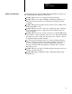
Unprotected Write . . . . . . . . . . . . . . . . . . . . . . . . . . . . . . . . . . . . . . . . . . . . . . . . . . . Protected Typed Logical Read with Three Address Fields (File, Element, Sub element) . . . . . . . . . . . . . . . . . . . . . . . . . . . . . . . . . . . . . . . . . . . . Protected Typed Logical Write with Three Address fields (File, Element, Sub element) . . . . . . . . . . . . . . . . . . . . . . . . . . . . . . . . . . . . . . . . . . . . Diagnostic Replies . . . . . . . . . . . . . .
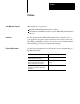
Preface Preface This Manual’s Purpose This manual shows you how to: Install the 6001-F2E Standard Driver software Communicate with DH-485 stations via the 6001-F2E Standard Driver software Audience Use this manual and the 6001-F2E Standard Driver software if any of your application programs require information from devices such as the SLC-500 programmable controller. We assume you are familiar with the DOS operating system and C programming language.
Chapter 1 Product Overview Why Use the Standard Driver Software? The Standard Driver Software (cat. no. 6001-F2E) for the 1784-KR Interface Module lets you communicate directly to SLC-500 programmable controllers and other devices on the DH-485 network. You use a standard set of function calls to communicate with DH-485 stations. These function calls let you define your own message packets or request pre-defined message packets included in the software.
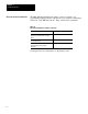
Chapter 1 Product Overview Overview of the Function Calls The 6001-F2E Standard Driver Software consists of a library of C programming language function calls that let your computer communicate with nodes on the DH-485 network. Table 1.A lists these commands: Table 1.
Chapter 1 Product Overview Software Considerations Important information about the 6001-F2E Standard Driver software for the 1784-KR Interface Module is listed below: the 6001-F2E driver does not support unsolicited messages the 6001-F2E does not support multiple outstanding commands (you must receive the reply from your command before sending another command) the 6001-F2E supports the large memory model version of Microsoft C and Borland Turbo C only the 6001-F2E driver does not respond to a diagnostic s
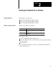
Chapter 2 Installing the Standard Driver Software Chapter Objectives In this chapter, you learn about: what the Standard Driver package includes the contents of the Standard Driver diskette how to install the Standard Driver Software What the Package Includes You have one of these two packages: Cat. No.
Chapter 2 Installing the Standard Driver Software What’s on the Diskette The Standard Driver diskette contains the following types of files: linkable large memory model standard driver library files application library files example application files Standard Driver Library Files Use the following files to build a linkable large memory model application using the Standard Driver. This file Contains L_MSKR.LIB a large memory model Microsoft v5.
Chapter 2 Installing the Standard Driver Software Example Files The following files contain working 6001-F2E Standard Driver application examples: Installing the Standard Driver Hardware and Software This file Contains F2EDIAG.C diagnostic routines F2ESLC.C unprotected read and unprotected write routines SCREEN.H definitions and declarations required to compile F2EDIAG.C or F2ESLC.C This section tells you how to install the Standard Driver hardware and software.
Chapter 2 Installing the Standard Driver Software Installing the Software To install the Standard Driver software: 1. Create a working directory in your computer’s hard disk (C:\F2E, for example). Use this directory to build your application program(s). 2. Put the disk containing the Standard Driver files in disk drive A:> (We use drive A:> as a default.) 3. Copy all the files from the disk to that directory (Copy A:*.* C:\F2E). This completes the installation procedure.
Chapter 3 Planning Your Application Program Chapter Objectives This section guides you through the process of planning an application program. It contains the following: include files you need to put in your program function calls programming considerations Include Files The include files contain declarations for the driver type you are using. Define them at the top of your application program. The 6001-F2E Standard Driver uses the following include files: KRDEFS.H STDDRV.
Chapter 3 Planning an Application Program Overview of the Function Calls Function calls let your application program communicate with devices on the DH-485 network: This Function Call Lets You Open_StdDrv() initialize the 6001-F2E Standard Driver. Use this function call in every program you write. Appl_StdDrv() use predefined support routines (Application Library) in applications that use the basic command set. See page 4-2 for a list of these commands.
Chapter 4 Using the Function Calls Chapter Objectives This chapter shows you how to use each of the function calls. It includes the format and parameters for each function call. Using Open_StdDrv() The Open_StdDrv() function call initializes the 6001-F2E Standard Driver.
Chapter 4 Writing Your Own Application Program Communicating on DH-485 with the 6001-F2E Standard Driver After you have initialized the Standard Driver with the Open_StdDrv() function call, you are ready to communicate. You can use the Appl_StdDrv() function call (Application Library) or the Send_StdDrv() function call or a combination of both. Use the SendStdDrv() function call to format commands not supported by the Application Library. See table 4.
Chapter 4 Writing Your Own Application Program Refer to Appendix B for each of the available Application Library routines. Table 4.C Appl_StdDrv() Message Block Data Structure Variable Type Description DHP_MSG.dev = device; char The device variable indicates to the Standard Driver the communication interface and its channel. Set this variable to KR:0. DHP_MSG.stat = &io_stat[0]; unsigned int The io_stat variable serves two purposes.
Chapter 4 Writing Your Own Application Program be interpretted by the SLC-500 as a logical offset (in words) into Data File 9. See the SLC-500 Advanced Programming Software Manual, chapter A3, for more information on the SLC-500 memory organization. Using Send_StdDrv() If you do not wish to use the commands supported by the Application Library, use the Send_StdDrv() function to send user-formatted messages. The Send_StdDrv() function call transmits data over the DH-485 network to a DH-485 station.
Chapter 4 Writing Your Own Application Program Parameters for Send_StdDrv() Assign the parameters in Table 4.D: Table 4.D Assigning Parameters to Send Data Parameter Type Description device[] = “KR:0” char The device parameter should coincide with the same device used in the Open_StdDrv() function (Set this value to KR:0.) io_stat[2]; The io_stat variable serves two purposes. When standard driver routines are called, they return status before any type of reply is received from the remote device.
Chapter 4 Writing Your Own Application Program Preventing Reply Messages from Being Lost To prevent reply messages from being lost, we provide a Get_tns() function. Use the following format: x = Get_tns() The Get_tns() function returns an unsigned integer value. Place this value in the two-byte TNS field of your DH-485 message prior to calling the Send_StdDrv() function. See page B-5 for more information on Get_tns().
Chapter 4 Writing Your Own Application Program Table 4.F Reading io_stat[0] If the STS and EXT STS bytes of io_stat[0] look like this STS EXT STS 0 Using Close_StdDrv() Command message. No error. The values in the EXT STS byte can be any values. 0 STS EXT STS F0 0B STS EXT STS X It is a Y Reply message with extended status information. Match the code in the low byte (EXT STS) to the code for the appropriate command in appendix D. Reply message.
Chapter 5 Compiling, Linking, and Configuring Your Application Program Chapter Objectives This chapter tells you what you need to do before your application program can communicate with other devices on the network. First, you compile and link the software, then configure it. See the instructions below. Compiling and Linking Your Application Program To compile and link the linkable driver application software, do the following: 1. Create your application program and “include” the KRDEFS.H and STDDRV.
Chapter 5 Compiling, Linking, and Configuring Your Application Program The following are compile line examples of Microsoft C and Borland Turbo C: Microsoft C C>CL /AL /Gs L_MSAPP.LIB L_MSKT.LIB Borland Turbo C C>TCC -ml L_TCAPP.LIB L_TCKT.LIB Configuring Your Application Program To configure your application program: 1. Type START485 followed by the communication option settings.
Appendix A Application Program Examples Sample Program /* /* /* /* The following program is an application that shows how to write information to Data File 9 of an SLC-500 processor using the Application Library and the PLC-2 (Unprotected Write) function symbol. If you are communicating to an SLC-500 using the unprotected read or unprotected write commands, you must first create Data File 9 in the SLC-500. The SLC-500 uses this file for DH-485 communication.
Appendix A Application Program Examples /* DH-485 function block description found in STDDRV.
Appendix A Application Program Examples /* Fct_stat returns 1 if F2E snet the command successfully if (fct_stat != NORMAL){ Get_ErrMsg(fct_stat, err_msg); printf(“%s/n”,err_msg); fct_stat = close_StdDrv(device); exit(1); } */ /* When a reply has been received or a timeout io_stat[0] will be set*/ while(!io_stat[0]); printf(“status reply received\n”); /* If io_stat[0] does not = 1 then an error occurred if (io_stat[0] != NORMAL){ Get_ErrMsg(io_stat[0],err_msg); printf(“%s/n”,err_msg); } fct_stat = Close_S
Appendix A Application Program Examples PLC-2 Unprotected Read /* ––––––––––––––––––––––––––––––––––––––––––––––––––– */ /* DH/DH+ Application Library (c) 1989 Allen–Bradley APPLICATION: PLC–2 Unprotected Read SYMBOL: PLC2_URD Include files: Linkable Driver: #include “krdefs.h” #include “stddrv.h” Application Variables: int size, PLC_FCT; d_buff[...
Appendix A Application Program Examples /* Call the Standard Driver Appl() function status = Appl_StdDrv( PLC_FCT, &DHP_MSG); /* status = See 6001–F2E User’s Manual appendix D */ io_stat[0]: Local & remote I/O status Hi_byte = DH-485 status Lo_byte = Local & extended DH-485 status io_stat[1]: Reply length in bytes (if applicable) Binary address format: dt_addr[0] = lo_byte, dt_addr[1] = hi_byte */ A-5
Appendix A Application Program Examples PLC-2 Unprotected Write /* ––––––––––––––––––––––––––––––––––––––––––––––––––– */ /* DH/DH+ Application Library (c) 1989 Allen–Bradley APPLICATION: PLC–2 Unprotected Write SYMBOL: PLC2_UWR Include files: Linkable Driver: #include “krdefs.h” #include “stddrv.h” Application Variables: int size, PLC_FCT; d_buff[...
Appendix A Application Program Examples /* Call the Standard Driver Appl() function status = Appl_StdDrv( PLC_FCT, &DHP_MSG); /*status = See 6001–F2E User’s manual appendix D */ io_stat[0]: Local & remote I/O status Hi_byte = DH-485 status Lo_byte = Local & extended DH-485 status io_stat[1]: Reply length in bytes (if applicable) Binary address format: dt_addr[0] = lo_byte, dt_addr[1] = hi_byte */ A-7
Appendix A Application Program Examples Diagnostic Loop Back /* ––––––––––––––––––––––––––––––––––––––––––––––––––––––––––––––––––– */ /* DH/DH+ Application Library (c) 1989 Allen–Bradley APPLICATION: Diagnostic Loop Back SYMBOL: PLCx_DLB Include files: Linkable Driver: #include “krdefs.h” #include “stddrv.h” Application Variables: int size, PLC_FCT; unsigned int status, io_stat[2], timeout; char device[]= “KR:0”; unsigned char destination; unsigned char d_buff[...
Appendix A Application Program Examples /* Call the Standard Driver Appl() function status = Appl_StdDrv( PLC_FCT, &DHP_MSG); /* status = See 6001–F2E User’s manual appendix D */ io_stat[0]: Local & remote I/O status Hi_byte = DH-485 status Lo_byte = Local & extended DH-485 status io_stat[1]: Reply length in bytes (if applicable) */ A-9
Appendix A Application Program Examples Diagnostic Counter Read /* ––––––––––––––––––––––––––––––––––––––––––––––––––––––––––––––––––– */ /* DH/DH+ Application Library (c) 1989 Allen–Bradley APPLICATION: Diagnostic Counter Read SYMBOL: PLCx_DCR Include files: Linkable Driver: #include “krdefs.h” #include “stddrv.h” Application Variables: int size, PLC_FCT; unsigned int status, io_stat[2], ctr_addr; timeout; char device[]= “KR:0”; unsigned char destination; unsigned char d_buff[...
Appendix A Application Program Examples PLC_FCT = PLCx_DCR; /* Initialize a PLC function /* Call the Standard Driver Appl() function status = Appl_StdDrv( PLC_FCT, &DHP_MSG); /* status = See 6001–F2E User’s manual appendix D */ */ io_stat[0]: Local & remote I/O status Hi_byte = DH-485 status Lo_byte = Local & extended DH-485 status io_stat[1]: Reply length in bytes (if applicable) */ A-11
Appendix A Application Program Examples Diagnostic Status /* ––––––––––––––––––––––––––––––––––––––––––––––––––––––––––––––––––– */ /* DH/DH+ Application Library (c) 1989 Allen–Bradley APPLICATION: Diagnostic Status SYMBOL: PLCx_DCR Include files: Linkable Driver: #include “krdefs.h” #include “stddrv.h” Application Variables: int size, PLC_FCT; unsigned int status, io_stat[2], timeout; char device[]= “KR:0”; unsigned char destination; unsigned char d_buff[...
Appendix A Application Program Examples PLC_FCT = PLCx_DS; /* Initialize a PLC function /* Call the Standard Driver Appl() function status = Appl_StdDrv( PLC_FCT, &DHP_MSG); /* status = See 6001–F2E User’s manual appendix D */ */ io_stat[0]: Local & remote I/O status Hi_byte = DH-485 status Lo_byte = Local & extended DH-485 status io_stat[1]: Reply length in bytes (if applicable) */ A-13
Appendix A Application Program Examples Diagnostic Counter Reset /* ––––––––––––––––––––––––––––––––––––––––––––––––––––––––––––––––––– */ /* DH/DH+ Application Library (c) 1989 Allen–Bradley APPLICATION: Diagnostic Counter Reset SYMBOL: PLCx_RC Include files: Linkable Driver: #include “krdefs.h” #include “stddrv.h” Application Variables: int size, PLC_FCT; unsigned int status, io_stat[2], timeout; char device[]= “KR:0”; unsigned char destination; unsigned char d_buff[...
Appendix A Application Program Examples PLC_FCT = PLCx_RC; /* Initialize a PLC function /* Call the Standard Driver Appl() function status = Appl_StdDrv( PLC_FCT, &DHP_MSG); /* status = See 6001–F2E User’s manual appendix D */ */ io_stat[0]: Local & remote I/O status Hi_byte = DH-485 status Lo_byte = Local & extended DH-485 status io_stat[1]: Reply length in bytes (if applicable) */ A-15
Appendix B Specifying Message Packet Commands with Send_StdDrv() Chapter Objectives Use the information in this appendix to format the Send_StdDrv() function call.
Appendix B Specifying Message Packet Commands with Send_StdDrv() Communicating with a Token-passing Device (SLC-500 Processor) Figure B.1 shows the message packet format you use to communicate with token-passing devices (such as an SLC-500 processor). Important: Shaded blocks indicate packet fields that may or may not be included in your message packet, depending on the command. Figure B.
Appendix B Specifying Message Packet Commands with Send_StdDrv() Communicating with a Slave-only Device Figure B.2 shows the message packet format you use to communicate with a slave-only DH-485 device. Important: Shaded blocks indicate packet fields that may or may not be included in your message packet, depending on the command. Figure B.2 Message Packet Format for Communicating with a Slave-only Device LEN TYP IMMED. 1 DST SRC CMD STS TNS TNS FNC ADDR SIZE DATA Table B.
Appendix B Specifying Message Packet Commands with Send_StdDrv() Message Packet Fields The message packet fields for the previous applications are described in more detail in the table below. Table B.C Message Packet Field Description Field Description LEN This field identifies the length of the message packet (including LEN). The allowed range is 0-255. TYP This is the code that identifies the type of communication.
Appendix B Specifying Message Packet Commands with Send_StdDrv() Field Description TNS The TNS (transaction) bytes (2 bytes) contain a unique 16-bit transaction identifier. For each command message transmitted by your computer node, your application level software must assign a unique 16-bit transaction number. A simple way to generate this number is to use the Get_tns() function and store the value in the two TNS bytes of the new message. See page 4-6 for more information on Get_tns().
Appendix B Specifying Message Packet Commands with Send_StdDrv() Supported Command Set The supported command set includes commands that can generally be executed by any SLC processor. Use these commands with the Send_StdDrv() function call.
Appendix B Specifying Message Packet Commands with Send_StdDrv() Diagnostic Counters Reset This command resets to zero all the diagnostic timers and counters in the node interface module. The diagnostic status command gives the starting address for this block of counters and timers Command Format CMD 06 STS TNS FNC 07 Reply Format CMD 46 Diagnostic Loop STS TNS You can use this command to check the integrity of the transmissions over the communication link.
Appendix B Specifying Message Packet Commands with Send_StdDrv() Diagnostic Read This command reads up to 244 bytes of data from the PROM or RAM of the node interface module. You can use it to read the module’s diagnostic timers and counters. When communicating to an SLC-500, set ADDR to 0 and SIZE to 10 (decimal). See appendix C for diagnostic read replies for DH-485 devices. Command Format CMD 06 STS TNS FNC 01 ADDR SIZE Reply Format CMD 46 Diagnostic Status STS TNS DATA 244 bytes max.
Appendix B Specifying Message Packet Commands with Send_StdDrv() Unprotected Read This command reads words of data from any area of PLC data table memory. Use the SIZE field to specify the number of bytes to be read. To specify a number of PLC words, SIZE should be an even value because PLC words are two bytes long. Data bytes are transferred low byte first. The address of a word should be even.
Appendix B Specifying Message Packet Commands with Send_StdDrv() Protected Typed Logical Read with Three Address Fields (File, Element, Sub-element) Byte No.: Command Format 1 CMD 0F 2 3,4 5 STS TNS FNC A2 6 7 8 BYTE FILE FILE SIZE NUMBER TYPE 9 10 ELEMENT SUB–ELMT. NUMBER NUMBER Table C.A gives a description of each field. Table B.
Appendix B Specifying Message Packet Commands with Send_StdDrv() Reply Format CMD 4F STS TNS EXT STS (only if error) DATA (244 bytes max) The following are possible STS and EXT STS responses. Table B.
Appendix B Specifying Message Packet Commands with Send_StdDrv() Protected Typed Logical Write with Three Address fields (File, Element, Sub-element) Byte No.: Command Format 1 2 3,4 5 6 7 8 CMD 0F STS TNS FNC AA FILE BYTE FILE SIZE NUMBER TYPE 9 10 ELEMENT SUB–ELMT. NUMBER NUMBER DATA 244 bytes max. Table B.F Protected Typed Logical Write with Three Address Fields Byte Description CMD 0F STS Indicates the status of a message transmission TNS A unique 16-bit transaction number.
Appendix C Diagnostic Replies Diagnostic Status Reply The tables below show diagnostic status replies for the following: SLC-5/01 (Table C.A) APS Software (Table C.B) 1784-KR Interface Module (Table C.C) Table C.
Appendix C Message Packet Formats for the Basic Command Set Byte Description 19 Processor Mode Status/Control Word – Bit 0-4 mode: – Bit 5 – Bit 6 – Bit 7 0 – Download 1 – Program 2 – Reserved 3 – Idle due to SUS instruction 4 – Reserved 5 – Reserved 6 – Run 7 – Test Continuous Scan 8 – Test Single Scan 9 – 31 Reserved Forces Active Forces Installed Communication Active Processor Mode Status/Control Word (High Byte) Bit 0 Bit 2 Bit 5 Protection Power Loss Load Memory Module on Mem Error Major Error
Appendix C Message Packet Formats for the Basic Command Set Table C.B Diagnostic Status Reply for APS Software (with COM1 Port DH-485 connection) Byte Description Status Reply (Hex) 1 Mode/Status Byte 00 (no modes) 2 Type Extender EE 3 Extended Interface Type 20 4 Extended Processor Type 1B 5 Series/Revision: Bits 0-4 Bits 5-7 0 (Release 1) 1 (Release 2). etc. 0 (Series A) 1 (Series B), etc. 6-16 Bulletin Number/Name= APS (ASCII) 17-24 Product Specific Information 00 Table C.
Appendix C Message Packet Formats for the Basic Command Set Diagnostic Read Reply (Diagnostic Counters) The table below contains diagnostic read reply values for: SLC-500 APS (COM1) 1784-KR Interface Module Table C.
Appendix D Error Codes Error Codes This appendix contains local and remote error codes: Table D.
Appendix D Error Codes Table D.B Remote Error Codes Error Codes (in Hex) Message STS 00 Success 10 Command format incorrect 50 Address problem 60 Disallowed due to command protection F0 Extended status EXT STS D-2 0B Access denied. Improper privilege 1A File already open 1B Procesor in edit mode.
Index A Application Library Files, 2-2 Application Program Compiling, Linking, and Configuring, 5-1 Examples, A-1 diagnostic counter read, A-10 diagnostic counter reset, A-14 diagnostic loop back, A-8 diagnostic status, A-12 plc-2 unprotected read, A-4 plc-2 unprotected write, A-6 sample program, A-1 Planning, 3-1 C Command Set, Supported, B-6 Diagnostic Counters Reset, B-7 Diagnostic Loop, B-7 Diagnostic Read, B-8 Diagnostic Status, B-8 protected typed logical with three address fields, B-10 protected ty
With offices in major cities worldwide WORLD HEADQUARTERS 1201 South Second Street Milwaukee, WI 53204 USA Tel: (414)382-2000 Telex: 43 11 016 FAX: (414)382-4444 EUROPE/INDIA/ MIDDLE EAST/AFRICA HEADQUARTERS Allen-Bradley Europa B.V. Amsterdamseweg 15 1422 AC Uithoorn The Netherlands Tel: (31)2975/60611 Telex: (844) 18042 FAX: (31)2975/60222 Publication 6001-6.5.5 – May 1990 Supercedes publication 6001-6.5.