
Owner manual

3
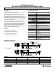
Wiring Diagrams (continued)
Models: 42SR_- 6_ _6 and 6_ _7
AC/DC All Models Except Transmitted Beam Source
Models:42SR_-6__4-QDand6__5-QD
White
Orange
Black
(+)
(--)
Models: 42SR_- 6_ _4 and 6_ _5
~
~
2 Red/White
3Red
1Red/Black
(+)
(--)
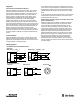
~
~
Brown
Black
Blue
(+)
(--)
~
~
Models:42SR_-6__6-QDand6__7-QD
2 Red/White
3Red
1Red/Black
(+)
(--)
42SRL- 6006- QD
Transmitted Beam Source
42SRL- 6006
Brown
Blue
(+)
(--)
2 Red/White
1Red/Black
(+)
(--)
T
T
~
~
~
~
13
2
4
AC/DC Pin Out
~
~
Looking at male pins.
Note: Details regarding connection of Allen-Bradley Series 6000 photoelectric sensors to Allen-Bradley Programmable Controllers can be found
in Publication 42SR-4.0.
All wire colors shown refer to Allen-Bradley quick-disconnect cables.
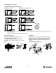
Supplied Accessories
Mounting Kit #129--106--1 contains 2 plastic nuts,
anti-vibration mount, and slip pads.
Mounting Kit #129--106--2 contains 2 plastic nuts,
anti-vibration mount, slip pads, and fiber optic mounting
hardware.
31.8
(1.25)
34.9
(1.375)
Dia.
Plastic Nuts
Series 6000 Sensor
Vibration Mount
Slip Pad
Slip
Pad
7.6
(0.30)
3.8
(0.15)
Plastic Nuts
1--20 UNEF
2A Thread
Installation
The 6000 Series sensor must be mounted on a firm, stable
surface or support. A mounting, which is subject to excessive
vibration or shifting may cause intermittent operation. For
installation convenience, we offer the following mounting
brackets.
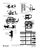
Swivel/Tilt Mounting Assembly #60- 2618
29.21
(1.15)
20.32
(0.8)
27.94 (1.1)
12.7
(0.5)
28.6
(1.125)
66.04
(2.6)
50.8
(2.0)
6.9 (0.270) Dia.
2Places