
Owner manual

Installation Instructions
PHOTOSWITCHr Series 6000 General Purpose Compact
IMPORTANT: SAVE THESE INSTRUCTIONS FOR FUTURE USE.
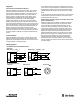
Description
Series 6000 photoelectric sensors provide reliable general
purpose sensing in a compact package.
Each Series 6000 sensor has a single red output indicator.
The Transmitted Beam Light Source has a red power
indicator. Each sensor has a clutch-protected four-turn
adjustment potentiometer . Each sensor can be supplied with a
3m (9.8ft) four or five conductor PVC cable or with a 4-pin DC
or AC micro-style quick disconnect on the end of a 300mm
(12in) length cable (“pigtail”).
Low voltage DC sensors have both NPN and PNP outputs
with 200ma output for each. Typical response is 1ms
Two AC/DC versions are available. The 20--132V AC/DC
sensor offers a single 300mA Power MOSFET output. The
20--264V AC/DC sensor offers a single 150mA Power
MOSFET output. Light operate or dark operate is selected by
catalog number for all Series 6000 sensors.
Features
S Compact cylindrical package
S Wide selection of sensing modes
S Universal supply voltage models
S Both NPN or PNP outputs (DC)
General Specifications
Light Source Infrared 880nm or visible red 650nm
Unit Protection Reverse Polarity, False Pulse
Supply Voltage 10--30V DC; 20-- 132V AC/DC; 20-- 264V AC/DC
Current Consumption 35mA maximum
Output Type Both NPN and PNP (DC); MOSFET (AC/DC)
Output Mode Light or dark operate by model
Housing Material Noryl
Lens Material Acrylic
LED Indicators Red: When on (or illuminated) the sensor output is
activated; when dark it is off.
Connection Types 3m 300V cable, 4-pin DC micro QD, 4-pin AC
micro QD
Supplied Accessories Mounting kit #129--106--1 and 129--106--2
Operating Environment IP67; NEMA 3, 4 X, 6, 12, 13
Vibration 10--55Hz, 1mm amplitude, meets or exceeds IEC
60947--5--2
Shock 30g with 1ms pulse duration, meets or exceeds
IEC 60947--5--2
Operating Temperature
-- 4 0 _Cto+56_C(--40_Fto+150_F)
Relative Humidity 95% max
Approvals UL listed, CSA approved, and CE marked for all
applicable directives
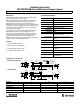
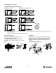
Dimensions—mm ( inches)
7.6
(0.30)
6.4
(0.25)
12.7
(0.50)
11.8
(0.465)
2.5
(0.10)
Max
3.6 (0.14) Dia.
Clearing for #6--32
HDW (2 holes)
14.61
(0.57)
14.61
(0.57)
3.6 (0.14) Dia.
Clearing for #6--32
HDW (2 holes)
5
(0.19)
12.7
(0.50)
14
(0.55)
6.4 (0.25)
All Models Except Fiber Optic
A
B
25.4
(1.00)
304
(12.0)
Fiber Optic Models
Rear
View
25.4
(1.00)
19
(0.75)
7.6
(0.30)
6.4 (0.25) 6.4 (0.25)
2.5
(0.10)
Max
34.93
(1.375)
34.93
(1.375)
6.4
(0.25)
6.4
(0.25)
6.4
(0.25)
3.8
(0.15)
C
A
BC
1--20 UNEF
2A Thread
1--20 UNEF
2A Thread
4TurnSensitivityPot
Red Indicator LED
4-Conductor Cable
3.2 (0.125) Dia.
M12 x 1
M12 x 1
304
(12.0)
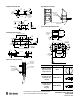
DC Models
A B C
All Except Fiber Optic
66 (2.60) 31.8 (1.25) 20.4 (0.81)
Fiber Optic 73.7 (2.90) 31.8 (1.25) 24.9 (1.05)
AC/DC Models
All Except Fiber Optic 91.4 (3.6) 57.2 (2.25) 20.4 (0.81)
Fiber Optic 99.1 (3.9) 57.2 (2.25) 24.9 (1.05)