
Accessories Manual


2
Installation
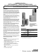
1. Remove the cover from the 42MTB Terminal Base
(Figures 1 and 2).
2. Remove four (4) screws from cover.
3. Install output module into terminal base . Note location
of the two holes for the Totalizer contact pins (Figure 1).
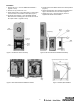
4. Mount #60--2072 Totalizer onto the 42MTB Terminal
Base so that the contacting pins fit into the two holes in
the output module (Figures 2 and 3).
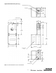
5. Set the internal reset disable s witch in the desired position
(Figure 3).
6. Remove bac king paper from vibration pad (supplied) and
apply to the side of the cover as shown in Figure 4.
7. Replace the cover using the longer (4) screws
supplied with the #60--2072 Totalizer.
42MR
Photohead
Output
module
Two holes for
contact pins
42MTB
terminal
base
#60--2072
Totalizer
42MTB
cover
(four) cover
screws
External
Reset
Six-digit display
Figure 1: Photoelectric sensor assembly Figure 2: #60--2072 PHOTOcountSWITCH assembly
Figure 3: #60--2072 PHOTOcountSWITCH Totalizer Figure 4: Vibration pad installation
Contact
pins
(Rear View)
Reset disable
switch
Lithium
battery
(Front View)
Locate vibration pad on inside of cover as shown
Cover
locating
holes
(Top)