
Instruction Manual
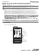

Control Terminals
The following table denes the E3 Overload Relay control terminal
designations.
Features are available only with the E3 Plus Overload Relay (cat. nos. 193/592-EC2 and
193/592-EC3).
Available only on cat. nos. 193/592-EC5_ _.
An earth ground connection to this terminal will assist in obtaining compliance with
electromagnetic compatibility requirements.
The use of shielded cable is recommended for the positive PTC thermistor circuit to assist
in obtaining compliance with electromagnetic compatibility requirements.
Available only on cat. nos. 193/592-EC3_ _ and 193/592-EC4_ _.
DeviceNet Terminals
The following table denes the DeviceNet connector terminal
designations.
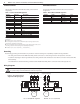
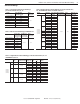
Table 1 - Control Terminal Designation
Termin al
Designation
Reference Description
1 IN 1 General-purpose sinking input number 1
2 IN 2 General-purpose sinking input number 2
3 IN 3 General-purpose sinking input number 3
4 IN 4 General-purpose sinking input number 4
5V+
+24V DC supply for inputs
6V+
7 IN 5 General-purpose sinking input number 5
8 IN 6 General-purpose sinking input number 6
End Earth Ground
13/14 OUT A Output A
23/24 OUT B Output B
95/96 Trip Relay Trip Relay
1T1/1T2 PTC Thermistor (PTC) input
S1/S2 -- External ground fault sensor input
Table 2 - DeviceNet Terminal Designation
Terminal Signal Function Color
BlackCommonV-1
BlueSignal Low
Signal High
CAN_L2
Non-insulatedShieldDrain3
WhiteCAN_H4
RedPower SupplyV+5
Grounding
The following grounding recommendations are provided to ensure electromagnetic compatibility compliance during installation:
· The earth ground terminal of the E3 Overload Relay shall be connected to a solid earth ground via a low-impedance connection.
· Installations employing an external ground fault sensor shall ground the cable shield at the sensor with no connection made at the E3 Plus
Overload Relay.
· The PTC thermistor cable shield shall be grounded at the E3 Plus Overload Relay with no connection made at the opposite end.
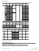
Wiring Diagrams
WARNING: When working on energized circuits, do not rely on the voltage and current information provided by the E3 and E3 Plus for personal safety. Always
use a portable voltage or current measurement device and measure the signal locally.
Bulletin 193 / 592 E3 and E3 Plus Solid State Overload Relay
2
Publication 193-IN055B-EN-P - August 2013 PN-154492 DIR 10000279804 (Version 01)
Figure 2 - Three-Phase D.O.L &
Single-Phase Wiring Diagrams
E3/E3 PlusE3/E3 Plus
L1 L2L1 L3L2
2/T1 6/T3
MM
S.C.P.D.
Single-Phase Full-VoltageThree-Phase Direct-On-Line
T2
T2
T3
T1
T1
L2 L3L1
Voltage Input Module
(For 193/592-EC5 only)
L2L1
Voltage Input Module
(For 193/592-EC5 only)
4/T22/T1 6/T34/T2