
User guide


3Ć2
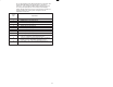
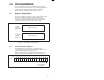
Model Connector
8132 J19
8140 J7 or J12
8142 JN
8530 JN
Figure 3.2Ć Toledo Scale Digital Indicator Xmit Connector
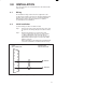
Step 3. Take the module out of its shipping container. Take it out of
the antiĆstatic bag, being careful not to touch the
connectors on the back of the module.
Step 4. Insert the module into the desired slot in the rack. Refer to
figure 3.3. Use a screwdriver to secure the module into the
slot.
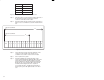
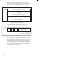
P/S
0123456789101112131415
10
Typical 10 Slot Rack
16
Typical 16 Slot Rack
Figure 3.3 Ć Rack Slot Numbers
Step 5. Connect the DĆshell on the end of the field wires to the
connector on the faceplate of the module. Use a
screwdriver to secure the connector to the module.
Step 6. Turn on power to the system.
Step 7. Verify the installation by checking the status of the
sevenĆsegment LED and the OK" light. When the power
is turned on, the module will automatically execute its
powerĆup diagnostics. After the module has finished its
diagnostics, the sevenĆsegment LED on the faceplate
should be off if the diagnostics were completed
successfully. The link is configured for 4800 baud on
powerĆup. The green OK" light should be on in either
case.