The information in this user's manual is subject to change without notice. WARNING THIS UNIT AND ITS ASSOCIATED EQUIPMENT MUST BE INSTALLED, ADJUSTED AND MAINTAINED BY QUALIFIED PERSONNEL WHO ARE FAMILIAR WITH THE CONSTRUCTION AND OPERATION OF ALL EQUIPMENT IN THE SYSTEM AND THE POTENTIAL HAZARDS INVOLVED. FAILURE TO OBSERVE THESE PRECAUTIONS COULD RESULT IN BODILY INJURY. WARNING INSERTING OR REMOVING THIS MODULE OR ITS CONNECTING CABLES MAY RESULT IN UNEXPECTED MACHINE MOTION.
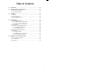
Table of Contents 1.0 Introduction . . . . . . . . . . . . . . . . . . . . . . . . . . . . . . . . . . . . . . . . . . . . . . . 1Ć1 2.0 Mechanical/Electrical Description . . . . . . . . . . . . . . . . . . . . . . . . . . . 2Ć1 $ " ( ' &) %$ . " )' " ( ' &) %$ . 3.0 Installation . . . . . . . . . . . . . . . . . . . . . . . . . . . .
II Technical Specifications . . . . . . . . . . . . . . . . . . . . . . . . . . . . . . . . . . . . . . AĆ1 Module Block Diagram . . . . . . . . . . . . . . . . . . . . . . . . . . . . . . . . . . . . . . BĆ1 Field Connections . . . . . . . . . . . . . . . . . . . . . . . . . . . . . . . . . . . . . . . . . . . CĆ1 Toledo Scale Continuous Output Message Format . . . . . . . . . . . . . . DĆ1 Defining Variables in the Configuration Task . . . . . . . . . . . . .
Figure 2.1 Figure 2.2 Ć Module Faceplate . . . . . . . . . . . . . . . . . . . . . . . . . . . . . . . . . . . . . 2Ć2 Ć LED Fault Codes . . . . . . . . . . . . . . . . . . . . . . . . . . . . . . . . . . . . . . 2Ć3 Figure 3.1 Figure 3.2 Figure 3.3 Ć Typical Field Signal Connections . . . . . . . . . . . . . . . . . . . . . . . . 3Ć1 Ć Toledo Scale Digital Indicator Xmit Connector . . . . . . . . . . . . 3Ć2 Ć Rack Slot Numbers . . . . . . . . . . . . . . . . . . . . . . . . . . . . . . .
fafadfdfdasfdsfdsdsdfdsfdsfdsfsdfdsa afdfdsfdsfdfdsfdsfsadfda asfdfaddfdd
The products described in this instruction manual are manufactured or distributed by Reliance Electric Company or its subsidiaries. The Toledo Scale Interface Module provides a single RSĆ232C serial I/O port for receiving data from Toledo Scale digital indicators (model numbers 8132, 8140, 8142, and 8530) that communicate via RSĆ232C with the Toledo Scale Continuous Output protocol. The serial data is stored in dual port memory where it can be read by application software.
fafadfdfdasfdsfdsdsdfdsfdsfdsfsdfdsa afdfdsfdsfdfdsfdsfsadfda asfdfaddfdd
2.0 MECHANICAL/ELECTRICAL DESCRIPTION The following is a description of the faceplate LEDs, field termination connectors, and electrical characteristics of the field connections. 2.1 Mechanical Description The Toledo Scale Interface module is a printed circuit board assembly that plugs into the backplane of the DCS5000/AutoMax rack. It consists of a printed circuit board, a faceplate, and a protective enclosure.
TOLEDO SCALE INTERFACE FAULT CODE OK DROP NUMBER 0 1ST 0 2ND Figure 2.
The 7Ćsegment LED provides detailed information on the status of the module. If the LED displays any number from 0" through 9" inclusive or b," the module is malfunctioning and has not passed one of its powerĆup diagnostics. Three other possible displays indicate that the module has not been set up properly or that there is a fault somewhere else in the system. See figure 2.2 for an explanation of fault codes.
fafadfdfdasfdsfdsdsdfdsfdsfdsfsdfdsa afdfdsfdsfdfdsfdsfsadfda asfdfaddfdd
3.0 INSTALLATION This section describes how to install and remove the module and its cable assembly. 3.1 Wiring The installation of wiring should conform to all applicable codes. To reduce the possibility of electrical noise interfering with the proper operation of the control system, exercise care when installing the wiring from the system to the external devices. For detailed recommendations refer to IEEE 518. 3.2 Initial Installation Use the following procedure to install the module: Step 1.
Model Connector 8132 J19 8140 J7 or J12 8142 JN 8530 JN Figure 3.2Ć Toledo Scale Digital Indicator Xmit Connector Step 3. Take the module out of its shipping container. Take it out of the antiĆstatic bag, being careful not to touch the connectors on the back of the module. Step 4. Insert the module into the desired slot in the rack. Refer to figure 3.3. Use a screwdriver to secure the module into the slot.
Step 8. Connect the programmer to the system and run the ReSource Software. Use the I/O MONITOR function. If a baud rate other than 4800 is required, configure the serial port by writing the baud rate used by the transmitting device to register 21 and then writing the value 255 to register 20. The sevenĆsegment LED should now be blank. Monitor registers 14,16,17 and 18 using the ReSource Software. Register 14 should be changing at the rate that messages are being received.
fafadfdfdasfdsfdsdsdfdsfdsfdsfsdfdsa afdfdsfdsfdfdsfdsfsadfda asfdfaddfdd
4.0 PROGRAMMING This section describes how data is organized in the module and provides examples of how the module is accessed by the application software. For more detailed information refer to the AutoMax Enhanced BASIC Language Instruction Manual (JĆ3675). 4.1 Register Organization The Toledo Scale Interface module contains a dual port memory that can be accessed by your application software as well as the microprocessor that controls the module.
Registers 14 through 18 contain information on the number and quality of messages received on the serial link. These counters will be incremented only if the startĆofĆmessage character (STX) is recognized by the module. Typically, these registers are used for diagnosing the serial link when problems occur. Refer to figure 4.3.
bits 15 14 13 12 11 10 register 21 9 8 7 6 5 4 3 2 1 0 baud rate (1200Ć9600) link timeĆout (1Ć10 seconds) 22 Figure 4.5Ć Control Registers register 23 register 24, 25 register 26, 27 register 28, 29 register 30, 31 register 32, 33 register 34, 35 register 36, 37 register 38, 39 Ć Ć Ć Ć Ć Ć Ć Ć Ć Setpoint Update Request Setpoint #1 Setpoint #2 Setpoint #3 Setpoint #4 Setpoint #5 Setpoint #6 Setpoint #7 Setpoint #8 Registers 24 through 39 may contain eight doubleĆinteger Setpoint values.
bits 15 14 13 12 11 10 register 64 9 8 7 6 5 4 3 2 1 0 request/status Value ă1 = User request to update information in registers 65Ć77. ă0 = Update completed without error. -1 = The checksum calculated by the module did not match the checksum character in the received message. -2 = A nonĆnumeric character was detected when converting the Indicated Weight or Tare Weight data to binary. -3 = A message with valid startĆofĆmessage and endĆofĆmessage characters did not contain 18 bytes.
Register 66 contains status byte A". Refer to figure 4.8. bits register 66 15 14 13 12 11 10 - - - - - - 9 8 7 6 5 4 3 2 1 0 - - - R 1 R R R R R Decimal pt. Location 0 = x100 1 = x10 2 = x1 3 = x.1 4 = x.01 5 = x.001 6 = x.0001 7 = x.00001 Model Dependent Model Dependent Model Dependent Figure 4.8Ć Status Byte A" Register 67 contains status byte B". Refer to figure 4.9.
Register 68 contains status byte C". Refer to figure 4.10. bits register 68 15 14 13 12 11 10 - - - - - - 9 8 7 6 5 4 3 2 1 0 - - - R 1 R R R R R Model Dependent Print Button Pushed Model Dependent Model Dependent Figure 4.10Ć Status Byte C" Registers 69Ć72 contain the indicated weight and tare weight, respectively. These values are stored as 32Ćbit long integers. See figure 4.11.
Two Gross Weight calculations are made by the Interface software. The `signed' Gross Weight is computed by first applying the `sign' bit from Status Word `B' to the Indicated Weight and then adding the Tare Weight. The result is stored as a double integer in registers 73, 74. The absolute value of the `signed' Gross Weight is stored in registers 75, 76. A comparison of the `signed' Gross Weight is made with each of the eight Setpoints in registers 24Ć39.
4.3.1 Configuring the Module The module must be configured whenever you turn on power to the system or change the baud rate of the serial interface. If the module has not been configured, it will display the letter C" on its LED. The following is an example of the BASIC statements required in an application task to configure the module. 400 410 420 430 440 450 480 490 600 610 620 630 1000 1010 1020 1030 1040 1050 1060 1070 4.3.
4.4 Message Transmission Time The time required for a message to be transmitted is: Time (in milliseconds) = 198,000/Baud Rate The module requires less than 1 millisecond to receive the message and store it in dual port memory. 4.5 Restrictions This section describes limitations and restrictions on the use of this module. 4.5.1 Remote Racks This module should not be used in a remote rack. 4.5.
fafadfdfdasfdsfdsdsdfdsfdsfdsfsdfdsa afdfdsfdsfdfdsfdsfsadfda asfdfaddfdd
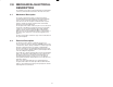
5.0 DIAGNOSTICS AND TROUBLESHOOTING This section explains how to troubleshoot the module and field connections. If you cannot determine the problem, the unit is not userĆserviceable. 5.1 No Activity on Serial Line Problem: No data is being received on the serial line. You can confirm this by monitoring the values in register 14Ć18. If they do not change regularly, no data is being received. The possible causes of this error are a programming error or a malfunctioning module.
If the transmitter is working correctly, repeat this process on the connector on the interface module. If the oscilloscope displays a square wave again, the interface module is malfunctioning. Otherwise, troubleshoot the cabling. Problem: The data is either always off, always on, or different than expected. The possible causes of this problem are a module in the wrong slot, a programming error, or a malfunctioning module.
time until the problem reappears. If none of these tests reveals the problem, replace the backplane. Problem: A 31" or 51"Ć54" appear on the processor module`s LED. These error messages indicate that there was a bus error when the system attempted to access the module. The possible causes of this error are a missing module, a module in the wrong slot, or a malfunctioning module. It is also possible that the user is attempting to write to readĆonly registers on the module.
fafadfdfdasfdsfdsdsdfdsfdsfdsfsdfdsa afdfdsfdsfdfdsfdsfsadfda asfdfaddfdd
Appendix A Technical Specifications Ambient Conditions Storage temperature: -40C Ć 85C Operating temperature: 0C Ć 60C Humidity:: 5Ć90% nonĆcondensing Maximum Module Power Dissipation 13 Watts Dimensions Height: 11.75 inches Width: 1.25 inches Depth: 7.
fafadfdfdasfdsfdsdsdfdsfdsfdsfsdfdsa afdfdsfdsfdfdsfdsfsadfda asfdfaddfdd
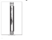
TOLEDO SCALE INTERFACE MODULE (57C428) Address ID BUS OK CPU Watchdog Address Decode Thumbwheel Switches 0 Address Bus BUS Dual Port Arbitration and Control Logic Wait Read Write 1 Z80 CPU LED Display Address Address and Control Bus Date 8K Byte Dual Port Memory 16K Byte EPROM 8K Byte RAM +5V +12V 4 Channel Counter Timer -12V Serial Interface XMIT RECV DTR 2 3 4 5 20 7 BĆ1
fafadfdfdasfdsfdsdsdfdsfdsfdsfsdfdsa afdfdsfdsfdfdsfdsfsadfda asfdfaddfdd
!
fafadfdfdasfdsfdsdsdfdsfdsfdsfsdfdsa afdfdsfdsfdfdsfdsfsadfda asfdfaddfdd
Appendix D Toledo Scale Continuous Output Message Format A valid message begins with a startĆofĆmessage character (ASCII STX). The message contains three bytes of status information, six bytes of indicated weight, and six bytes of tare weight. The message is terminated by a carriage return. A single byte checksum follows the carriage return. The checksum is calculated by taking the 2's complement of the sum of bits 0Ć6 of all characters preceding the checksum character.
fafadfdfdasfdsfdsdsdfdsfdsfdsfsdfdsa afdfdsfdsfdfdsfdsfsadfda asfdfaddfdd
Appendix E Defining Variables in the Configuration Task Before any application programs can be written, it is necessary to configure, or set, the definitions of systemĆwide variables, i.e. those that must be globally accessible to all tasks. This section describes how to configure the system variables on this input module. Refer to the figure below. Note that this procedure is only used if you are using the Programming Executive Software Version 2.1 or earlier.
16 Bit Register Reference Use the following method to reference a 16 bit register. 16 bit register reference is commonly used to reference message number and status. The symbolic name of each register should be as meaningful as possible. nnnnnăIODEFăSYMBOLIC_NAME%[ SLOT=s, REGISTER=r] Bit Reference Use the following method to reference individual inputs on the module. Single bit reference is used to reference link status. The symbolic name of each bit should be as meaningful as possible.
fafadfdfdasfdsfdsdsdfdsfdsfdsfsdfdsa afdfdsfdsfdfdsfdsfsadfda asfdfaddfdd
For additional information 1 Allen-Bradley Drive Mayfield Heights, Ohio 44124 USA Tel: (800) 241-2886 or (440) 646-3599 http://www.reliance.com/automax Publication J-3644-2 - June 1991 Copyright © 2002 Rockwell Automation, Inc.. All rights reserved. Printed in U.S.A.