Common Memory Module (M/N 57C413B) (M/N 57C423) Instruction Manual JĆ3636Ć2
The information in this user's manual is subject to change without notice. DANGER ONLY QUALIFIED ELECTRICAL PERSONNEL FAMILIAR WITH THE CONSTRUCTION AND OPERATION OF THIS EQUIPMENT AND THE HAZARDS INVOLVED SHOULD INSTALL, ADJUST, OPERATE, AND/OR SERVICE THIS EQUIPMENT. READ AND UNDERSTAND THIS MANUAL IN ITS ENTIRETY BEFORE PROCEEDING. FAILURE TO OBSERVE THIS PRECAUTION COULD RESULT IN SEVERE BODILY INJURY OR LOSS OF LIFE. WARNING INSERTING OR REMOVING A MODULE MAY RESULT IN UNEXPECTED MACHINE MOTION.
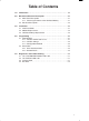
Table of Contents 1.0 Introduction . . . . . . . . . . . . . . . . . . . . . . . . . . . . . . . . . . . . . . . . . . . . . . . 1Ć1 2.0 Mechanical/Electrical Description . . . . . . . . . . . . . . . . . . . . . . . . . . . 2.1 Mechanical Description . . . . . . . . . . . . . . . . . . . . . . . . . . . . . . . . . . . 2.1.1 Checking the Status of the OnĆBoard Battery . . . . . . . . . . 2.2 Electrical Description . . . . . . . . . . . . . . . . . . . . . . . . . . . . . . . . . . . . .
Appendices Appendix A Technical Specifications . . . . . . . . . . . . . . . . . . . . . . . . . . . . . . . . . . . . . . AĆ1 Appendix B Module Block Diagram . . . . . . . . . . . . . . . . . . . . . . . . . . . . . . . . . . . . . . BĆ1 Appendix C Configuring the Common Memory Module in DCS 5000 or AutoMax V 2.1 or Earlier Systems . . . . . . . . . . . . . . . . . . . . . . . . . . . . . CĆ1 Appendix D Summary of Common Memory Module Features . . . . . . . . . . . . . . . .
List of Figures Figure 2.1 Ć Module Faceplate . . . . . . . . . . . . . . . . . . . . . . . . . . . . . . . . . . . . . 2Ć2 Figure 3.1 Ć Rack Slot Numbers . . . . . . . . . . . . . . . . . . . . . . . . . . . . . . . . . . .
afadfdfdasfdsfdsdsdfdsfdsfdsfsdfdsa fdfdsfdsfdfdsfdsfsadfda sfdfaddfdd
1.0 INTRODUCTION The products described in this instruction manual are manufactured or distributed by Reliance Electric Industrial Company. The Common Memory module (57C413B and 57C423) is required in slot 0 of a DCS 5000/AutoMax rack that contains more than one Processor module. The Common Memory module stores the configuration data that must be shared among Processors, such as definitions of physical I/O. This frees Processor module memory for application tasks.
D JĆ3684 ReSource AutoMax PROGRAMMING EXECUTIVE INSTRUCTION MANUAL VERSION 2.0 D JĆ3750 ReSource AutoMax PROGRAMMING EXECUTIVE INSTRUCTION MANUAL VERSION 3.
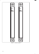
2.0 MECHANICAL/ELECTRICAL DESCRIPTION The following is a description of the faceplate LEDs and the basic circuit functions on the module. 2.1 Mechanical Description The Common Memory module is a printed circuit board assembly that plugs into the backplane of the DCS 5000/AutoMax rack. The module consists of a printed circuit board, a faceplate, and a protective enclosure. The faceplate contains tabs at the top and bottom to simplify removing the module from the rack.
COMMON MEMORY MODULE 57C413B COMMON MEMORY MODULE 57C423 BAT.OK BAT.OK Figure 2.
2.2 Electrical Description The Common Memory module incorporates the bus arbitration logic required when there are two or more Processor modules in a rack. Note that bus arbitration logic is enabled only when the module is in slot 0. The bus arbitration logic will support up to a maximum of four Processors located in slots 1Ć4. The bus arbiter resolves the contention problem that arises when two or more Processors attempt to access the backplane bus at the same time.
afadfdfdasfdsfdsdsdfdsfdsfdsfsdfdsa fdfdsfdsfdfdsfdsfsadfda sfdfaddfdd
3.0 INSTALLATION This section describes how to install and remove the module and the onĆboard battery. Note that removing or replacing the Common Memory module may affect tasks and variables in the rack. Appendix E illustrates how tasks and variables are affected in a DCS 5000 rack. Appendix F illustrates how tasks and variables are affected in an AutoMax rack.
Typical 16 Slot Rack 16 Typical 10 Slot Rack P/S 0 1 2 10 3 4 5 6 7 8 9 10 11 12 13 14 15 Figure 3.1 Ć Rack Slot Numbers Step 5. Turn on power to the rack. Step 6. Verify the installation. If the Common Memory module was placed in slot 0, the powerĆup diagnostics performed automatically by a Processor module should verify that the module is operational. If the Common Memory module is placed in any even slot other than 0, it must be manually tested like a standard I/O module.
module. Place the module in the cardboard shipping container. Step 5. Take the new module out of the antiĆstatic bag, being careful not to touch the connectors on the back of the module. Step 6. Activate the battery by taking it out of its holder and removing the tape that covers it. Replace the battery in its holder. Make certain that the battery is facing in the proper direction, i.e., the end marked +" on the battery is facing the end marked +" on the battery holder. Step 7.
3Ć4 Step 4. Take the old battery out of the holder. Remove the tape from the new battery and insert the battery in the holder. Make certain that the battery is facing the proper direction, i.e., the end marked +" on the battery is facing the end marked +" on the battery holder. Step 5. ReĆinsert the module into the correct slot in the rack. Use a screwdriver to secure the module into the rack. Step 6. Turn on power to the rack. The BAT. OK" LED should be lit.
4.0 PROGRAMMING This section describes how the data is organized in the module and provides examples of how the module is accessed by the application software. The Common Memory module has two distinct modes of operation depending on the slot that it is in. If the module is located in slot 0, the bus arbitration logic and watchdog timer are enabled and the module is controlled entirely by the leftĆmost Processor module.
4.1.2 Variable Storage Local variables are stored on the Processor module in which the application task that declares them will run. Common variables are stored on the Processor module, unless there is a Common Memory module in slot 0 of the rack, in which case the common variables are stored on the Common Memory module instead. This frees up memory on the Process module for application tasks.
4.2.1 Rack Slot Restrictions A Common Memory module is required in slot 0 in a rack that contains more than one Processor module. The slot to the right of the Common Memory module must either be empty or contain a Processor module for M/N 57C413B. For M/N 57C423, the 3 slots to the right of the module must either be empty or contain a Processor module. This module may also be plugged into even slots (2,4,6,8,10,12, or 14).
afadfdfdasfdsfdsdsdfdsfdsfdsfsdfdsa fdfdsfdsfdfdsfdsfsadfda sfdfaddfdd
5.0 DIAGNOSTICS AND TROUBLESHOOTING This section explains how to troubleshoot the Common Memory module. 5.1 The SYSTEM WATCHDOG" LED is Off Problem: The green SYSTEM WATCHDOG" LED on a Common Memory module located in slot 0 is off, and a Processor module in the rack displays codes 4.0 through 4.6. These error codes mean that the Common Memory module has failed one of its powerĆup diagnostics. Systematically swap out the Common Memory module and the Processor module(s).
empty or contain a Processor module. If this is not the case, multiple modules will respond to references. If the module is not in slot 0, i.e., it is serving as data storage, verify that the definition statements in the configuration are associated with the correct slots. Step 2. Verify that the variables are being referenced correctly. Verify that all tasks that reference variables on this module declare them COMMON. Only one task should be writing to any one variable. Step 3.
program. Verify that any IOREAD functions and IOWRITE statements are using valid addresses. If IOREAD functions and IOWRITE statements are using valid addresses or if the error message in question was 51" through 58", use the I/O MONITOR function to display the registers on the memory module. Remember to specify the correct logical slot. If you can monitor the inputs, the problem lies in the application software (proceed to step 3).
afadfdfdasfdsfdsdsdfdsfdsfdsfsdfdsa fdfdsfdsfdfdsfdsfsadfda sfdfaddfdd
Appendix A Technical Specifications Ambient Conditions D Storage temperature: -40oC Ć 85oC D Operating temperature: 0oC Ć 60oC D Humidity: 5Ć90% nonĆcondensing Maximum Module Power Dissipation D 5.3 Watts Dimensions D Height: 11.75 inches D Width: 1.25 inches D Depth: 7.375 inches System Power Requirements D +5 volts: 1050 mA Battery Specifications D Type: Lithium D Size: AA D Voltage: 3.6 Volts D Amp Hrs.: 2.
afadfdfdasfdsfdsdsdfdsfdsfdsfsdfdsa fdfdsfdsfdfdsfdsfsadfda sfdfaddfdd
Appendix B Module Block Diagram Common Memory Module (57C413 and 57C423) Common Memory Module (57C413) ADDRESS ID BUS BUS ADDRESS BUS SYSTEM WATCHDOG SLOT 0 BUS CLOCK OK ADDRESS DECODER DIAGNOSTICS OK EVEN SLOT WDOG OK BD RESET INITIALIZE BYTE HI EN CONTROL LOGIC WRITE MEM READ WRITE READ MEM RAM MEMORY YACK 64K x 16 = M/N 57C413B 128K x 16 = M/N 57C423 BAT.
afadfdfdasfdsfdsdsdfdsfdsfdsfsdfdsa fdfdsfdsfdfdsfdsfsadfda sfdfaddfdd
Appendix C Configuring the Common Memory Module in DCS 5000 or AutoMax V 2.1 or Earlier Systems In DCS 5000 or AutoMax Version 2.1 or earlier systems, a configuration task must be created and loaded onto the Processor(s) in the rack before any application task can be executed. The configuration task defines all common variables, i.e., variables that are accessible to more than one application task in the rack (physical inputs/outputs and memory variables).
Appendix C (Continued) 1000 NVMEMDEF WINDOW%, STOPPB@ The NVMEMDEF statement also allows you to define array variables. The following example defines an array of 20 (0Ć19) singleĆprecision integers with the name SIZES%". 1650 NVMEMDEF SIZES%(19) Common Memory Module Located in Any Even Slot Other Than 0 This section describes how to configure the Common Memory module when it is located in any even slot other than 0. In this situation the Common Memory module provides userĆconfigurable data storage only.
Appendix C (Continued) 16 Bit Register Reference Format Use the following method to reference a 16 bit register as a single precision integer. One statement is required in the configuration task for each variable. The symbolic name of each value should be as meaningful as possible: nnnnn IODEF SYMBOLIC_NAME%[ SLOT=s, REGISTER=r] Bit Reference Format Use the following method to reference individual bits in a register. One statement is required in the configuration task for each variable.
afadfdfdasfdsfdsdsdfdsfdsfdsfsdfdsa fdfdsfdsfdfdsfdsfsadfda sfdfaddfdd
Appendix D Summary of Common Memory Module Features M/N 57C413 This module has 128K bytes of memory and requires external battery backup (M/N 57C492) to mainain the contents of memory in the event of a power failure. M/N 57C413B This module has 128K bytes of memory and an onĆboard lithium battery to maintain the contents of memory in the event of a power failure.
afadfdfdasfdsfdsdsdfdsfdsfdsfsdfdsa fdfdsfdsfdfdsfdsfsadfda sfdfaddfdd
Appendix E How Removing/Replacing The Common Memory Module Affects Tasks and Variables in a DCS 5000 Rack The following tables illustrate how removing or replacing the Common Memory module affects tasks and variables in a DCS 5000 rack. (Refer to Appendix F for information regarding the effect on tasks and variables in an AutoMax rack.) In each case, assume a BASIC task has written to variables in both the Processor (local) and the Common Memory module (common).
Appendix E (Continued) The Common Memory Module Is In Any Even Slot Other Than 0 In the following, assume the Common Memory module is in slot 2 and the single Processor module in the rack is in slot 1. Recall that in this configuration, common variables, as well as local variables, are being stored on the Processor module. Status of Data Common App. Task Deleted? App.
Appendix F How Removing/Replacing The Common Memory Module Affects Tasks and Variables in an AutoMax Rack The following tables illustrate how removing or replacing the Common Memory module affects tasks and variables in an AutoMax rack. (Refer to Appendix E for information regarding the effect on tasks and variables in a DCS 5000 rack.) In each case, assume a BASIC task has written to variables in both the Processor (local) and the Common Memory module (common).
Appendix F (Continued) The Common Memory Module Is In Any Even Slot Other Than 0 In the following, assume the Common Memory module is in slot 2 and the single Processor module in the rack is in slot 1. Recall that in this configuration, common variables, as well as local variables, are being stored on the Processor module. Status of Data Common App. Task Deleted? App.
afadfdfdasfdsfdsdsdfdsfdsfdsfsdfdsa fdfdsfdsfdfdsfdsfsadfda sfdfaddfdd
Publication J-3636-2 - May 1992 Copyright © 2002 Rockwell Automation, Inc.. All rights reserved. Printed in U.S.A.