
Owner manual
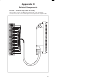

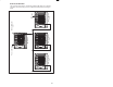

Table Of Contents
- J-3623-3 115 VAC High Power Output Module
- Warning Notices
- Table of Contents
- List of Figures
- 1.0 Introduction
- 2.0 Mechanical/Electrical Description
- 3.0 Installation
- 4.0 Programming
- 5.0 Diagnostics and Troubleshooting
- A Technical Specifications
- B Module Block Diagram
- C Field Connections
- D Related Components
- E Defining Variables in the Configuration Task
- Back Cover
EĆ1
Appendix E
Defining Variables in the
Configuration Task
Local I/O Definition
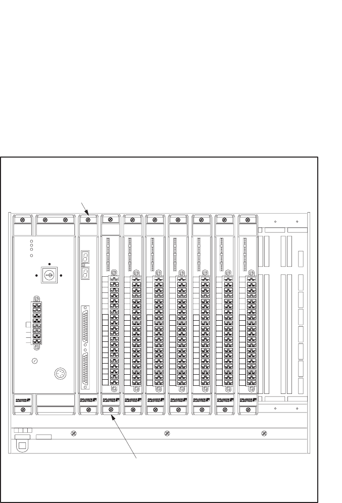
This section describes how to configure the output module when it is located in
the same rack (i.e., the local rack) as the processor module that is referencing it.
Refer to the figure below. Note that this procedure is used only if you are using
the AutoMax Programming Executive software version 2.1 or earlier.
1
0
2
3
4
C1
5
6
7
C2
8
9
10
11
C3
12
13
14
15
C4
B
C
DE
F
G
1
2
3
6
7
8
B
C
DE
F
G
1
2
3
6
7
8
275 W
POWER
SUPPLY
1
0
2
3
4
C1
5
6
7
C2
8
9
10
11
C3
12
13
14
15
C4
B
C
DE
F
G
1
2
3
6
7
8
1
0
2
3
4
C1
5
6
7
C2
8
9
10
11
C3
12
13
14
15
C4
B
C
DE
F
G
1
2
3
6
7
8
1
0
2
3
4
C1
5
6
7
C2
8
9
10
11
C3
12
13
14
15
C4
B
C
DE
F
G
1
2
3
6
7
8
120V
LINK
GND
L2
L1
FUSE
BATTERY
BACKĆUP
POWER ON
P/S READY
SYSTEM READY
BLOWN FUSE
NORMAL
REMOTE
PROGRAM
57491
Processor Module
B
C
DE
F
G
1
2
3
6
7
8
1
0
2
3
4
C1
5
6
7
C2
8
9
10
11
C3
12
13
14
15
C4
B
C
DE
F
G
1
2
3
6
7
8
1
0
2
3
4
C1
5
6
7
C2
8
9
10
11
C3
12
13
14
15
C4
B
C
DE
F
G
1
2
3
6
7
8
I/O Module
OUTPUT
0
1
2
3
4
5
6
7
8
9
10
11
12
14
14
15
1
0
2
3
4
C1
5
6
7
C2
8
9
10
11
C3
12
13
14
15
C4
0
1
2
3
4
5
6
7
8
9
10
11
12
14
14
15
0
1
2
3
4
5
6
7
8
9
10
11
12
14
14
15
0
1
2
3
4
5
6
7
8
9
10
11
12
14
14
15
0
1
2
3
4
5
6
7
8
9
10
11
12
14
14
15
0
1
2
3
4
5
6
7
8
9
10
11
12
14
14
15
0
1
2
3
4
5
6
7
8
9
10
11
12
14
14
15
Module in a Local Rack