
Owner manual
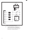
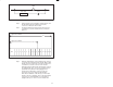
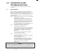
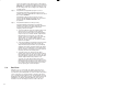
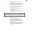

Table Of Contents
- J-3623-3 115 VAC High Power Output Module
- Warning Notices
- Table of Contents
- List of Figures
- 1.0 Introduction
- 2.0 Mechanical/Electrical Description
- 3.0 Installation
- 4.0 Programming
- 5.0 Diagnostics and Troubleshooting
- A Technical Specifications
- B Module Block Diagram
- C Field Connections
- D Related Components
- E Defining Variables in the Configuration Task
- Back Cover
3Ć2
1
2
3
4
5
TB
1A
1A
1A
1A
OUT
IN
SOLENOID VALVE
CONTACTOR
115 VAC
FU
AC LINE
SOLENOID
VALVE
Figure 3.1 Ć Typical Field Signal Connections
Step 4. If the device to which you are connecting the output
module contains an inductive load, install an RC
suppression network across the output terminals of the
device. If this is not done, the output module may not
always function correctly. Refer to figure 3.2.