WARNING THIS UNIT AND ITS ASSOCIATED EQUIPMENT MUST BE INSTALLED, ADJUSTED AND MAINTAINED BY QUALIFIED PERSONNEL WHO ARE FAMILIAR WITH THE CONSTRUCTION AND OPERATION OF ALL EQUIPMENT IN THE SYSTEM AND THE POTENTIAL HAZARDS INVOLVED. FAILURE TO OBSERVE THESE PRECAUTIONS COULD RESULT IN BODILY INJURY. WARNING INSERTING OR REMOVING THIS MODULE OR ITS CONNECTING CABLES MAY RESULT IN UNEXPECTED MACHINE MOTION.
Table of Contents 1.0 Introduction . . . . . . . . . . . . . . . . . . . . . . . . . . . . . . . . . . . . . . . . . . . . . . . 1Ć1 2.0 Mechanical/Electrical Description . . . . . . . . . . . . . . . . . . . . . . . . . . . 2Ć1 $ # "% ! ) %# $ # "% ! ) 3.0 Installation . . . . . . . . . . . . . . . . . . . . . . . . . . . . . .
II Technical Specifications . . . . . . . . . . . . . . . . . . . . . . . . . . . . . . . . . . . . . . AĆ1 Module Block Diagram . . . . . . . . . . . . . . . . . . . . . . . . . . . . . . . . . . . . . . BĆ1 Field Connections . . . . . . . . . . . . . . . . . . . . . . . . . . . . . . . . . . . . . . . . . . . CĆ1 Related Components . . . . . . . . . . . . . . . . . . . . . . . . . . . . . . . . . . . . . . . .
$! ) ' $# $# ! $ # ) $! ) $ # ) $! ) ' # " ) $! ) $ ! "" #& ! ! $ # % " ) $! ) # $ !"
fafadfdfdasfdsfdsdsdfdsfdsfdsfsdfdsa afdfdsfdsfdfdsfdsfsadfda asfdfaddfdd
The products described in this instruction manual are manufactured or distributed by Reliance Electric Company or its subsidiaries. This 115 VAC High Power Output Module will drive a maximum of sixteen 115 volt control signals as outputs from the DCS 5000/AutoMax system. The output signal frequency may be either 50 or 60 hertz. Individual outputs are rated at a maximum current of 2 amps. Outputs have high inrush capacity for handling capacitive loads.
fafadfdfdasfdsfdsdsdfdsfdsfdsfsdfdsa afdfdsfdsfdfdsfdsfsadfda asfdfaddfdd
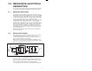
2.0 MECHANICAL/ELECTRICAL DESCRIPTION The following is a description of the faceplate LEDs, field termination connectors, and electrical characteristics of the field connections. 2.1 Mechanical Description The output module is a printed circuit board assembly that plugs into the backplane of the DCS 5000/AutoMax rack. It consists of a printed circuit board, a faceplate, and a protective enclosure. The faceplate contains tabs at the top and bottom to simplify removing the module from the rack.
the status of the logic level circuitry. A lit LED indicates that data has been written to the output. See figure 2.2. 115V AC HIGH OUTPUT 0 1 2 3 4 5 6 7 8 9 10 11 12 13 14 15 D E C B 0 1 1 2 2 3 3 4 L1 5 4 6 5 7 6 8 7 9 L2 1 0 8 1 1 9 1 2 10 1 3 11 1 4 L3 1 5 12 1 6 13 1 7 14 1 8 15 1 9 L4 2 0 3 2 F G 1 8 6 7 Figure 2.
3.0 INSTALLATION This section describes how to install and remove the module and its cable assembly. 3.1 Wiring The installation of wiring should conform to all applicable codes. To reduce the possibility of electrical noise interfering with the proper operation of the control system, exercise care when installing the wiring from the system to the external devices. For detailed recommendations refer to IEEE 518. 3.2 Initial Installation Use the following procedure to install the module: Step 1.
AC LINE FU 115 VAC TB SOLENOID VALVE 1 1A CONTACTOR 2 1A 3 SOLENOID VALVE IN 1A 4 OUT 1A 5 Figure 3.1 Ć Typical Field Signal Connections Step 4. 3Ć2 If the device to which you are connecting the output module contains an inductive load, install an RC suppression network across the output terminals of the device. If this is not done, the output module may not always function correctly. Refer to figure 3.2.
COIL 2200 ohms 600v .5 f Figure 3.2 Ć RC Suppression Network for Inductive Loads Step 5. Take the module out of its shipping container. Take it out of the antiĆstatic bag, being careful not to touch the connectors on the back of the module. Step 6. Insert the module into the desired slot in the rack. Use a screwdriver to secure the module into the slot. Refer to figure 3.3. Typical 16 Slot Rack 16 Typical 10 Slot Rack P/S 0 1 2 10 3 4 5 6 7 8 9 10 11 12 13 14 15 Figure 3.
rack be rotated one position to the right of the keys on the preceding module. If you use this method, the keys on a particular connector will be positioned in such a way as to fit together only with a specific module, and there will be little chance of the wrong connector being attached to a module. Step 8. Turn on power to the system. Step 9. Verify the installation by connecting the programming terminal to the system and running the ReSource Software. Stop all programs that may be running.
4.0 PROGRAMMING This section describes how data is organized in the module and provides examples of how the module is accessed by the application software. For more detailed information, refer to the AutoMax Enhanced BASIC Language Instruction Manual (JĆ3675). 4.1 Register Organization The data in the module is organized as one 16 bit register.
Ladder logic and control block tasks read inputs once at the beginning of each scan and write outputs once at the end of each scan. BASIC tasks read an input and write an output for each reference throughout the scan. 4.3.1 Ladder Logic Task Example light STARTPL RUN 1050 RUN The symbolic names RUN and STARTPL reference the output modules that were defined in the configuration. The trailing at symbol @" is not used in ladder logic tasks.
5.0 DIAGNOSTICS AND TROUBLESHOOTING This section explains how to troubleshoot the module and field connections. 5.1 Incorrect Data Problem: The device connected to theoutput is either always off, always on, or acting different than expected. The possible causes of this are a module in the wrong slot, a programming error, or a malfunctioning module. It is also possible that the output is either not wired or wired to the wrong device. Use the following procedure to isolate the problem: Step 1.
Connect a voltmeter to the proper points on the terminal strip and continue to toggle the output device from the I/O MONITOR. The voltmeter should alternate between 0 and the line voltage. If this does not happen, the output circuit is malfunctioning. Step 5. Verify that the user application program is correct. Verify that the application program that references the symbolic names associated with the module has declared those names COMMON.
Step 1. Verify that the output module is in the correct slot and that the I/O definitions are correct. Refer to figure 3.2. Verify that the slot number being referenced agrees with the slot number defined in the configuration task. Verify that the register number is 0. Note that the bit number and the wire number are not the same. For remote I/O installations, also verify that the master slot and remote drop number are defined correctly. Step 2. Verify that the module can be accessed.
fafadfdfdasfdsfdsdsdfdsfdsfdsfsdfdsa afdfdsfdsfdfdsfdsfsadfda asfdfaddfdd
Appendix A Technical Specifications Ambient Conditions D Storage temperature: -40_C Ć 85_C D Operating temperature: 0_C Ć 60_C D Humidity: 5Ć90% nonĆcondensing Maximum Module Power Dissipation D 30 Watts Dimensions D Height: 11.75 inches D Width: 1.25 inches D Depth: 7.375 inches System Power Requirements D +5 volts: 1200 ma Output Circuit D Number of outputs: 16 D Maximum operating voltage: 132 volts rms D On state voltage drop: 1.
fafadfdfdasfdsfdsdsdfdsfdsfdsfsdfdsa afdfdsfdsfdfdsfdsfsadfda asfdfaddfdd
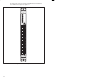
115 VAC HIGH OUTPUT MODULE (57C403) ADDRESS ID BUS BUS ADDRESS ADDRESS DECODER BUS 0 ISOL OUTPUT SWITCH ISOL OUTPUT SWITCH ISOL OUTPUT SWITCH ISOL OUTPUT SWITCH 1 WDOG OK 2 BD RESET INITIALIZE 3 CONTROL LOGIC BYTE HI EN WRITE MEM XFER ACK 4 GATE RESET GATE 2 3 GATE OUTPUT DATA BUFFER ISOL OUTPUT SWITCH 4 ISOL OUTPUT SWITCH 5 ISOL OUTPUT SWITCH 6 ISOL OUTPUT SWITCH 7 5 BIT INPUT DATA BUFFER OUTPUT BUFFER 0 1 2 3 4 5 6 7 8 9 10 11 12 13 14 15
fafadfdfdasfdsfdsdsdfdsfdsfdsfsdfdsa afdfdsfdsfdfdsfdsfsadfda asfdfaddfdd
Appendix C Field Connections Terminal Board Number Reg.
fafadfdfdasfdsfdsdsdfdsfdsfdsfsdfdsa afdfdsfdsfdfdsfdsfsadfda asfdfaddfdd
Appendix D Related Components 57C370 - Terminal Strip/Cable Assembly This assembly consists of a NEMAĆstyle terminal strip, cable, and mating connector. It is used to connect field signals to the faceplate of the output module.
Appendix D (Continued) 61C505 - DINĆStyle Terminal Strip/Cable Assembly (Fused) This assembly consists of a DINĆstyle terminal strip with fuses, cable, and mating connector. It is used to connect field signals to the faceplate of the output module.
Appendix D (Continued) 61C506 - DINĆStyle Terminal Strip/Cable Assembly (Unfused) This assembly consists of a DINĆstyle terminal strip with fuses, cable, and mating connector. It is used to connect field signals to the faceplate of the output module.
fafadfdfdasfdsfdsdsdfdsfdsfdsfsdfdsa afdfdsfdsfdfdsfdsfsadfda asfdfaddfdd
Appendix E Defining Variables in the Configuration Task Local I/O Definition This section describes how to configure the output module when it is located in the same rack (i.e., the local rack) as the processor module that is referencing it. Refer to the figure below. Note that this procedure is used only if you are using the AutoMax Programming Executive software version 2.1 or earlier.
Use the following method to reference all 16 outputs as a single register. Only one statement is required in the configuration task for the entire module. The symbolic name of the register should be as meaningful as possible: nnnnn IODEF SYMBOLIC_NAME%[ SLOT=s, REGISTER=0] Use the following method to reference individual outputs on the module. For the entire module, a maximum of 16 statements can be included in the configuration task (one for each bit).
! # % ! # % ! # % ! "" ! $ "# ! ! # "# ! $ " " # " ! " & # $! # $# $# $ & # " # ! # # " ! # ! # ! "" ! $ ! ! # ! # # $! & $ # '
Use the following method to reference all 16 outputs as a single register. Only one statement is required in the configuration task for the entire module. The symbolic name of the register should be as meaningful as possible: nnnnn RIODEF SYMBOLIC_NAME%[ MASTER_SLOT=m, SLOT=s, REGISTER=0] DROP=d, For the entire module, a maximum of 16 statements can be included in the configuration task (one for each bit).
fafadfdfdasfdsfdsdsdfdsfdsfdsfsdfdsa afdfdsfdsfdfdsfdsfsadfda asfdfaddfdd
For additional information 1 Allen-Bradley Drive Mayfield Heights, Ohio 44124 USA Tel: (800) 241-2886 or (440) 646-3599 http://www.reliance.com/automax Publication J-3623-3 - July 1993 Copyright © 2002 Rockwell Automation, Inc.. All rights reserved. Printed in U.S.A.