
Instruction Manual


EĆ1
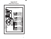
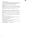
This section describes how to configure the output module when it is located in
the same rack (i.e., the local rack) as the processor module that is referencing it.
Refer to the figure below. Note that this procedure is used only if you are using
the AutoMax Programming Executive software version 2.1 or earlier.
1
0
2
3
4
C1
5
6
7
C2
8
9
10
11
C3
12
13
14
15
C4
B
C
DE
F
G
1
2
3
6
7
8
B
C
DE
F
G
1
2
3
6
7
8
275 W
POWER
SUPPLY
1
0
2
3
4
C1
5
6
7
C2
8
9
10
11
C3
12
13
14
15
C4
B
C
DE
F
G
1
2
3
6
7
8
1
0
2
3
4
C1
5
6
7
C2
8
9
10
11
C3
12
13
14
15
C4
B
C
DE
F
G
1
2
3
6
7
8
1
0
2
3
4
C1
5
6
7
C2
8
9
10
11
C3
12
13
14
15
C4
B
C
DE
F
G
1
2
3
6
7
8
120V
LINK
GND
L2
L1
FUSE
BATTERY
BACKĆUP
POWER ON
P S READY
SYSTEM READY
BLOWN FUSE
NORMAL
REMOTEPROGRAM
57491
Processor Module
I/O Module
B
C
DE
F
G
1
2
3
6
7
8
1
0
2
3
4
C1
5
6
7
C2
8
9
10
11
C3
12
13
14
15
C4
B
C
DE
F
G
1
2
3
6
7
8
1
0
2
3
4
C1
5
6
7
C2
8
9
10
11
C3
12
13
14
15
C4
B
C
DE
F
G
1
2
3
6
7
8
0
1
2
3
4
5
6
7
8
9
10
11
12
13
14
15
1
0
2
3
4
C1
5
6
7
C2
8
9
10
11
C3
12
13
14
15
C4
0
1
2
3
4
5
6
7
8
9
10
11
12
13
14
15
0
1
2
3
4
5
6
7
8
9
10
11
12
13
14
15
0
1
2
3
4
5
6
7
8
9
10
11
12
13
14
15
0
1
2
3
4
5
6
7
8
9
10
11
12
13
14
15
0
1
2
3
4
5
6
7
8
9
10
11
12
13
14
15
0
1
2
3
4
5
6
7
8
9
10
11
12
13
14
15
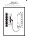
OUTPUT
Module in a Local Rack