
Instruction Manual


3Ć1
This section describes how to install and remove the module and its
cable assembly.
The installation of wiring should conform to all applicable codes.
To reduce the possibility of electrical noise interfering with the proper
operation of the control system, exercise care when installing the
wiring from the system to the external devices. For detailed
recommendations refer to IEEE 518.
Use the following procedure to install the module:
Step 1. Turn off power to the system. All power to the rack as well
as all power to the wiring leading to the module should be
off.
Step 2. Mount the terminal strip (M/N 57C370) on a panel. The
terminal strip should be mounted to permit easy access to
the screw terminals on the terminal strip. Make certain that
the terminal strip is close enough to the rack so that the
cable will reach between the terminal strip and the
module.
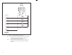
Step 3. Fasten field wires to the terminal strip. Note that the bit
number and wire number are not the same. Refer to
Appendix C for the arrangement of terminal strip
connections. Make certain that all field wires are securely
fastened. Typical field signal connections are shown in
figure 3.1.