
Instruction Manual


2Ć2
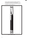
There are 16 LEDs on the faceplate of the module. The LEDs are
arranged in the same order as the output terminals on the faceplate.
They are numbered sequentially from zero through fifteen,
corresponding to the bits in the register. The LED indicators display
the status of the logic level circuitry. A lit LED indicates that data has
been written to the output. See figure 2.2.
115V AC/DC
LOW OUTPUT
57C402
1
0
2
3
4
L1
5
6
7
L2
8
9
10
11
L3
12
13
14
15
L4
B
C
DE
F
G
1
2
3
6
7
8
0
1
2
3
4
5
6
7
8
9
10
11
12
13
14
15
1
2
3
4
5
6
7
8
9
1
1
0
1
1
1
1
1
1
1
6
7
2
3
4
5
1
8
1
9
2
0
Figure 2.2 Ć Module Faceplate