The information in this user's manual is subject to change without notice. WARNING THIS UNIT AND ITS ASSOCIATED EQUIPMENT MUST BE INSTALLED, ADJUSTED AND MAINTAINED BY QUALIFIED PERSONNEL WHO ARE FAMILIAR WITH THE CONSTRUCTION AND OPERATION OF ALL EQUIPMENT IN THE SYSTEM AND THE POTENTIAL HAZARDS INVOLVED. FAILURE TO OBSERVE THESE PRECAUTIONS COULD RESULT IN BODILY INJURY. WARNING INSERTING OR REMOVING THIS MODULE OR ITS CONNECTING CABLES MAY RESULT IN UNEXPECTED MACHINE MOTION.
Table of Contents 1.0 Introduction . . . . . . . . . . . . . . . . . . . . . . . . . . . . . . . . . . . . . . . . . . . . . . . 1Ć1 2.0 Mechanical/Electrical Description . . . . . . . . . . . . . . . . . . . . . . . . . . . 2Ć1 2.1 Mechanical Description . . . . . . . . . . . . . . . . . . . . . . . . . . . . . . . . . . . 2Ć1 2.2 Electrical Description . . . . . . . . . . . . . . . . . . . . . . . . . . . . . . . . . . . . . 2Ć1 3.0 Installation . . . . . . . . . . . . . . . . . . . . . . . . . . . .
! # " # ! # ! ! # ! " !
Figure 2.1 Figure 2.2 Ć Typical Output Circuit . . . . . . . . . . . . . . . . . . . . . . . . . . . . . . . . . . 2Ć1 Ć Module Faceplate . . . . . . . . . . . . . . . . . . . . . . . . . . . . . . . . . . . . . 2Ć2 Figure 3.1 Figure 3.2 Ć Typical Field Signal Connections . . . . . . . . . . . . . . . . . . . . . . . . 3Ć2 Ć Rack Slot Numbers . . . . . . . . . . . . . . . . . . . . . . . . . . . . . . . . . . . 3Ć3 Figure 4.1 Ć Organization of Register Bits . . . . . . . . . . . . . . . .
fafadfdfdasfdsfdsdsdfdsfdsfdsfsdfdsa afdfdsfdsfdfdsfdsfsadfda asfdfaddfdd
The products described in this instruction manual are manufactured or distributed by Reliance Electric Company or its subsidiaries. This 24Ć115V AC/DC Low Power Output Module will drive a maximum of sixteen control signals as outputs from the DCS 5000/AutoMax system. The output signal voltage may range from 24Ć115 volts and DC through 60 hertz. Maximum output current is limited to 200 ma. Leakage current is less than 1 ma. Output signals have 2500 volt isolation to logic common.
fafadfdfdasfdsfdsdsdfdsfdsfdsfsdfdsa afdfdsfdsfdfdsfdsfsadfda asfdfaddfdd
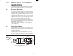
The following is a description of the faceplate LEDs, field termination connectors, and electrical characteristics of the field connections. The output module is a printed circuit board assembly that plugs into the backplane of the DCS 5000/AutoMax rack. It consists of a printed circuit board, a faceplate, and a protective enclosure. The faceplate contains tabs at the top and bottom to simplify removing the module from the rack.
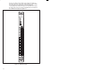
There are 16 LEDs on the faceplate of the module. The LEDs are arranged in the same order as the output terminals on the faceplate. They are numbered sequentially from zero through fifteen, corresponding to the bits in the register. The LED indicators display the status of the logic level circuitry. A lit LED indicates that data has been written to the output. See figure 2.2.
This section describes how to install and remove the module and its cable assembly. The installation of wiring should conform to all applicable codes. To reduce the possibility of electrical noise interfering with the proper operation of the control system, exercise care when installing the wiring from the system to the external devices. For detailed recommendations refer to IEEE 518. Use the following procedure to install the module: Step 1.
$".+ 2 1*$ & $ & $"( & )(( -$)(, 2 - * % -# ') .& ).- )! $-, ,#$**$(" )(- $( + % $- ).- )! -# (-$2,- -$ " $(" + !.& ()- -) -). # -# )(( -)+, )( -# % )! -# ') .& - * (, +- -# ') .& $(-) -# ,$+ ,&)- $( -# + % , , + 0 +$/ + -) , .+ -# ') .& $(-) -# ,&)- ! + -) !$".
Typical 16 Slot Rack 16 Typical 10 Slot Rack P/S 0 1 2 10 3 4 5 6 7 8 9 10 11 12 13 14 15 Figure 3.2 Ć Rack Slot Numbers Step 6. Attach the field terminal connector (M/N 57C370) to the mating half on the module. Make certain that the connector is the proper one for this module. Use a screwdriver to secure the connector to the module. Note that both the module and the terminal strip connector are equipped with keys.
WARNING BE CAREFUL WHEN WRITING TO THE OUTPUTS TO INSURE THAT NO UNEXPECTED MACHINE MOTION WILL RESULT. FAILURE TO OBSERVE THIS PRECAUTION COULD RESULT IN BODILY INJURY OR DAMAGE TO EQUIPMENT. 3.3 Module Replacement Use the following procedure to replace a module: 3Ć4 Step 1. Turn off power to the rack and all connections. Step 2. Use a screwdriver to loosen the screws holding the connector to the module. Remove the connector. Step 3. Loosen the screws holding the module to the rack.
4.0 PROGRAMMING This section describes how data is organized in the module and provides examples of how the module is accessed by the application software. For more detailed information, refer to DCS 5000 Enhanced BASIC Language Instruction Manual (JĆ3600) or AutoMax Enhanced BASIC Language Instruction Manual (JĆ3675). 4.1 Register Organization The data in the module is organized as one 16 bit register.
The frequency with which tasks, or application programs, read their inputs and write their outputs depends on the language being used. Ladder logic and control block tasks read inputs once at the beginning of each scan and write outputs once at the end of each scan. BASIC tasks read an input and write an output for each reference throughout the scan.
!"* * +"'& /($ "&* !'. +' +)', $ *!''+ +! %' ,$ & " $ '&& +"'&* )' $ % ! -" '&& + +' +! ',+(,+ "* "+! ) $. 0* ' $. 0* '& ') +"& " ) &+ +! & /( + ! ('**" $ ,* * ' +!"* ) %' ,$ "& +! .)'& *$'+ ()' ) %%"& ))') ') % $ ,& +"'&"& %' ,$ + "* $*' ('**" $ +! + +! ',+(,+ "* "+! ) &'+ .") ') .") +' +! .)'& -" * +! '$$'.
WARNING BE CAREFUL WHEN WRITING TO THE OUTPUTS TO INSURE THAT NO UNEXPECTED MACHINE MOTION WILL RESULT. FAILURE TO OBSERVE THIS PRECAUTION COULD RESULT IN BODILY INJURY OR DAMAGE TO EQUIPMENT. Step 4. Verify that the output circuit on the module is working correctly. Connect a voltmeter to the proper points on the terminal strip and continue to toggle the output device from the I/O MONITOR. The voltmeter should alternate between 0 and the line voltage.
5.2 Bus Error Problem: A 31" or 51" through 58" appears on the processor module's LED. This error message indicates that there was a bus error when the system attempted to access the module. This error message means that the module is missing, in the wrong slot, or malfunctioning. It is also possible that that user has attempted to write to the wrong registers on the module.
fafadfdfdasfdsfdsdsdfdsfdsfdsfsdfdsa afdfdsfdsfdfdsfdsfsadfda asfdfaddfdd
Appendix A Technical Specifications Ambient Conditions D Storage temperature: -40_ C Ć 85_ C D Operating temperature: 0_ C Ć 60_ C D Humidity: 5Ć90% nonĆcondensing Maximum Module Power Dissipation D 20 Watts Dimensions D Height: 11.75 inches D Width: 1.25 inches D Depth: 7.375 inches System Power Requirements D +5 volts: 525 ma D +12 volts: 45 ma D -12 volts: 45 ma Input Circuit D Number of outputs: 16 D Maximum operating voltage: 132 volts rms D On state voltage drop: 1.4 volts at minimum current 2.
fafadfdfdasfdsfdsdsdfdsfdsfdsfsdfdsa afdfdsfdsfdfdsfdsfsadfda asfdfaddfdd
115 AC/DC LOW OUTPUT MODULE (57C402) ADDRESS ID BUS BUS ADDRESS ADDRESS DECODER BUS 0 ISOL OUTPUT SWITCH ISOL OUTPUT SWITCH ISOL OUTPUT SWITCH ISOL OUTPUT SWITCH 1 WDOG OK 2 BD RESET INITIALIZE 3 CONTROL LOGIC BYTE HI EN WRITE MEM XFER ACK 4 GATE RESET GATE 2 3 GATE OUTPUT DATA BUFFER ISOL OUTPUT SWITCH 4 ISOL OUTPUT SWITCH 5 ISOL OUTPUT SWITCH 6 ISOL OUTPUT SWITCH 7 5 BIT INPUT DATA BUFFER OUTPUT BUFFER 0 1 2 3 4 5 6 7 8 9 10 11 12 13 14 15
fafadfdfdasfdsfdsdsdfdsfdsfdsfsdfdsa afdfdsfdsfdfdsfdsfsadfda asfdfaddfdd
Appendix C Field Connections Terminal Board Number Reg.
fafadfdfdasfdsfdsdsdfdsfdsfdsfsdfdsa afdfdsfdsfdfdsfdsfsadfda asfdfaddfdd
57C370 - Terminal Strip/Cable Assembly This assembly consists of a terminal strip, cable, and mating connector. It is used to connect field signals to the faceplate of the output module.
fafadfdfdasfdsfdsdsdfdsfdsfdsfsdfdsa afdfdsfdsfdfdsfdsfsadfda asfdfaddfdd
This section describes how to configure the output module when it is located in the same rack (i.e., the local rack) as the processor module that is referencing it. Refer to the figure below. Note that this procedure is used only if you are using the AutoMax Programming Executive software version 2.1 or earlier.
Use the following method to reference the entire module as a single register. Only one statement is required in the configuration task for the entire module. The symbolic name of the register should be as meaningful as possible: nnnnn IODEF SYMBOLIC_NAME%[ SLOT=s, REGISTER=0] Use the following method to reference individual bits on the module. For the entire module, a maximum of 16 statements can be included in the configuration task (one for each bit).
Remote I/O Slave Drop 7 Remote I/O Slave Drop 2 Remote I/O Slave Drop 1 Master Rack Processor Module Remote I/O Master Drop 0 I/O Module This section describes how to configure the output module when it is located in a rack that is remote from the processor module referencing it. Refer to the figure below.
Single Register Reference Use the following method to reference the entire module as a single register. Only one statement is required in the configuration task for the entire module. The symbolic name of the register should be as meaningful as possible: nnnnn RIODEF SYMBOLIC_NAME%[ MASTER_SLOT=m, DROP=d, SLOT=s,ă& REGISTER=0] Bit Reference Use the following method to reference individual bits on the module.
fafadfdfdasfdsfdsdsdfdsfdsfdsfsdfdsa afdfdsfdsfdfdsfdsfsadfda asfdfaddfdd
For additional information 1 Allen-Bradley Drive Mayfield Heights, Ohio 44124 USA Tel: (800) 241-2886 or (440) 646-3599 http://www.reliance.com/automax Publication J-3624-1 - June 1991 Copyright © 2002 Rockwell Automation, Inc.. All rights reserved. Printed in U.S.A.