
User guide


V
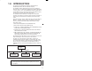
Figure 1.1 Ć A Typical Coaxial Cable Remote I/O Network 1Ć1.............
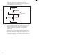
Figure 1.2 Ć A Typical FiberĆOptic Cable Remote I/O Network 1Ć2..........
Figure 1.3 Ć Multiple Remote I/O Network Connections (Coax) 1Ć3.........
Figure 2.1 Ć Remote I/O Module Faceplate 2Ć2..........................
Figure 2.2 Ć AutoMax Remote I/O Shark Interface Module Faceplate 2Ć3....
Figure 2.3 Ć AutoMax Remote I/O Head Faceplate (M/N 57C328 and
M/N 57330) 2Ć5..........................................
Figure 2.4 Ć AutoMax Remote Drive Interface Head Faceplate 2Ć8.........
Figure 2.5 Ć Remote I/O Network Drop Numbers 2Ć11.....................
Figure 2.6 Ć Mutually Exclusive Drop Numbers 2Ć12.......................
Figure 3.1 Ć Remote I/O Network Coaxial Cable System 3Ć3..............
Figure 3.2 Ć Communications Passive Tap 3Ć4...........................
Figure 3.3 Ć Coaxial Cable 3Ć4........................................
Figure 3.4 Ć Dual Crimp BNC Plug Connector 3Ć5.......................
Figure 3.5 Ć BNC Tee Adapter 3Ć5.....................................
Figure 3.6 Ć 75 Ohm Terminating Load 3Ć6..............................
Figure 3.7 Ć BNC JackĆtoĆJack Adapter 3Ć6.............................
Figure 3.8 Ć Ferrule on the RGĆ59/U Cable 3Ć10..........................
Figure 3.9 Ć RGĆ59/U (Belden 9259) Cable Stripping Dimensions 3Ć10.......
Figure 3.10 Ć Connector Installation Step 3 for RGĆ59/U Cable 3Ć11..........
Figure 3.11 Ć Connector Installation Step 6 for RGĆ59/U Cable 3Ć12..........
Figure 3.12 Ć Connector Installation Step 7 for RGĆ59/U 3Ć12................
Figure 3.13 Ć Connector Installation Step 8 for RGĆ59/U Cable 3Ć12..........
Figure 3.14 Ć Connector Installation Step 9 for RGĆ59/U Cable 3Ć13..........
Figure 3.15 Ć Connector Attached to RGĆ59/U Cable 3Ć13...................
Figure 3.16 Ć Cable Splicing 3Ć14........................................
Figure 3.17 Ć Mounting Dimensions 3Ć19.................................
Figure 3.18 Ć Mounting Examples 3Ć20...................................
Figure 3.19 Ć Grounding Stud Location 3Ć21..............................
Figure 3.20 Ć Grounding the Remote Head 3Ć22...........................
Figure 3.21 Ć 120 VAC or 240 VAC Input Power Connections 3Ć23...........
Figure 3.22 Ć Connecting the Remote I/O Head to the FiberĆ
Optic Network 3Ć24........................................
Figure 3.23 Ć Connecting the Remote Drive Interface Head to the
FiberĆOptic Network 3Ć26...................................
Figure 3.24 Ć Ready Relay 3Ć28.........................................
Figure 3.25 Ć Typical EĆStop Circuit Using Ready Contacts 3Ć28.............
Figure 3.26 Ć Adding a New Rack Drop to the End of the Remote I/O
Network (Coax) 3Ć33.......................................
Figure 3.27 Ć Adding an Intermediate Rack Drop to the Remote I/O
Network (Coax) 3Ć34.......................................
Figure 3.28 Ć Disconnecting an End Rack Drop from the Remote I/O
Network (Coax) 3Ć35.......................................
Figure 3.29 Ć Disconnecting an Intermediate Rack Drop from the
Remote I/O Network (Coax) 3Ć35............................
Figure 4.1 Ć Drop 0 Status Register Assignments 4Ć2.....................
Figure 4.2 Ć Shark I/O Module Configuration Word 4Ć5...................
Figure 4.3 Ć Sample Coaxial Cable Remote I/O Network With Multibus
Rack and Remote I/O Head Drops 4Ć9......................
Figure 4.4 Ć Sample Coaxial Cable Remote I/O Network With Shark
Rack Drops 4Ć12..........................................