
User guide

3Ć20
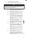
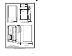
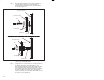
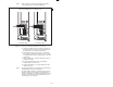
Step 2. Mount the Remote I/O Head on the panel and attach it
securely with #10 (M5) bolts or studs. Examples of
attaching the Remote I/O Head to the mounting surface
are shown in figure 3.18.
TAPPED HOLE
STAR WASHER
BOLT
MOUNTING FLANGE
MOUNTING FLANGE
MOUNTING SURFACE
BACK PANEL
NUT .218" DIA.
.218" DIA.
STAR WASHER
WELDED STUD
Figure 3.18 Ć Mounting Examples
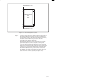
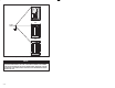
Step 3. Using figure 3.19, locate the two No. 10 studs provided on
the Remote I/O Head for grounding purposes. The
Remote I/O Head must be properly grounded to minimize
personnel hazard and to ensure proper operation. The
ground path, when using a 1KVA transformer, should have
less than 10 milliohms resistance. The grounding wire
must be a minimum size of 14 AWG. The insulation should
be green for U.S.A. applications.