
User guide

3Ć13
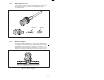
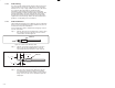
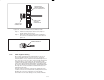
TYPICAL BNC
CONNECTOR
FERRULE ON
ANVIL OF
CRIMPING DIE
SHOULDER ON
CONNECTOR BODY
BUTTS AGAINST DIE
Figure 3.14 Ć Connector Installation Step 9 for RGĆ59/U Cable
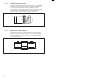
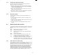
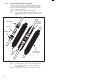
Step 10. Hold the assembly in place and close the crimp tool
handles until the rachet releases.
Step 11. Remove the crimped assembly from the crimping dies.
The connector is now attached to the coaxial cable. See
figure 3.15.
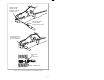
CRIMPED FERRULE
Figure 3.15 Ć Connector Attached to RGĆ59/U Cable
Once a cable segment has been terminated with a connector on
each end, visually inspect the connector for loose connections,
nicked insulation, or loose strands from the braid that might cause a
poor connection or short. The center contact should be straight and
centered inside the connector dielectric. Be sure that the center
conductor is inserted deep enough into the connector body. The tip
of the center contact should be approximately even with the end of
the connector dielectric. Be sure the ferrule is crimped tightly against
the body of the connector and that the shield braid wire does not
protrude from the ferrule.
Check the cable's mechanical connections by grasping the outer
conductor connector in one hand and the coaxial jacket in the other.
Pull firmly. The connectors should hold. Use a time domain
reflectometer to test for cable damage, shorts, and discontinuities.