The information in this manual is subject to change without notice. DANGER ONLY QUALIFIED ELECTRICAL PERSONNEL FAMILIAR WITH THE CONSTRUCTION AND OPERATION OF THIS EQUIPMENT AND THE HAZARDS INVOLVED SHOULD INSTALL, ADJUST, OPERATE, OR SERVICE THIS EQUIPMENT. READ AND UNDERSTAND THIS MANUAL AND OTHER APPLICABLE MANUALS IN THEIR ENTIRETY BEFORE PROCEEDING. FAILURE TO OBSERVE THIS PRECAUTION COULD RESULT IN SEVERE BODILY INJURY OR LOSS OF LIFE.
Table of Contents 1.0 Introduction . . . . . . . . . . . . . . . . . . . . . . . . . . . . . . . . . . . . . . . . . . . . . . . 1.1 Related Publications . . . . . . . . . . . . . . . . . . . . . . . . . . . . . . . . . . . . . 1.2 Related Hardware and Software . . . . . . . . . . . . . . . . . . . . . . . . . . . 1.3 Terms and Conventions Used in This Manual . . . . . . . . . . . . . . . . 1Ć1 1Ć4 1Ć5 1Ć5 2.0 Mechanical/Electrical Description . . . . . . . . . . . . . . . . . . . . . . . . . . . 2.
3.6 3.7 3.8 3.9 II 3.5.4 Installing the Remote Drive Interface Head (M/N 57C329) . . . . . . . . . . . . . . . . . . . . . . . . . . . . . . . . . . . . . 3.5.5 Remote I/O Network EmergencyĆStop Considerations . . Module Replacement . . . . . . . . . . . . . . . . . . . . . . . . . . . . . . . . . . . . . 3.6.1 Replacing the Remote I/O Module (M/N 57C416) . . . . . . . 3.6.2 Replacing the Shark Interface Module (M/N 57C554) . . . 3.6.3 Replacing the Remote I/O Head (M/N 57C328 and M/N 57C330) . . . . . .
6.0 Diagnostics And Troubleshooting . . . . . . . . . . . . . . . . . . . . . . . . . . . 6.1 The Remote I/O Module's OK LED is Off . . . . . . . . . . . . . . . . . . . . 6.2 Error Code A is on the Remote I/O Module's 7ĆSegment Display . . . . . . . . . . . . . . . . . . . . . . . . . . . . . . . . . . . . . . . 6.3 Remote I/O Network Failures . . . . . . . . . . . . . . . . . . . . . . . . . . . . . . 6.4 The Shark Interface Module's CPU OK LED is Off . . . . . . . . . . . . 6.
Figure 1.1 Figure 1.2 Figure 1.3 Ć A Typical Coaxial Cable Remote I/O Network . . . . . . . . . . . . . 1Ć1 Ć A Typical FiberĆOptic Cable Remote I/O Network . . . . . . . . . . 1Ć2 Ć Multiple Remote I/O Network Connections (Coax) . . . . . . . . . 1Ć3 Figure 2.1 Figure 2.2 Figure 2.3 Figure 2.4 Figure 2.5 Figure 2.6 Ć Remote I/O Module Faceplate . . . . . . . . . . . . . . . . . . . . . . . . . . Ć AutoMax Remote I/O Shark Interface Module Faceplate . . . .
VI Figure 5.1 Ć Drop Status Monitoring . . . . . . . . . . . . . . . . . . . . . . . . . . . . . . . . 5Ć1 Figure 6.1 Ć AutoMax Rail Fault LED Codes . . . . . . . . . . . . . . . . . . . . . . . . .
Appendices Appendix A * / * "'# % ) # # ,#('+ 1 Appendix B %( $ # !* &+ 1 Appendix C 1 (*, #'(-, 1 Appendix D &(, **(* ( + 1 Appendix E " & ,# +
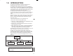
The products described in this manual are manufactured or distributed by Reliance Electric Industrial Company. The AutoMaxr Remote I/O network interconnects an AutoMax or DCS 5000 Processor with remote AutoMax racks, Remote I/O Heads, or remote Sharkt racks. The AutoMax Remote I/O Communications module (M/N 57C416) is the interface between the AutoMax or DCS 5000 Processor and the remote I/O on the network. The AutoMax Remote I/O network is designed for master/slave operation.
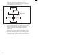
The fiberĆoptic cable network is organized in an active star configuration. With this type of topology, each node is connected to a multiĆport central point, also referred to as a hub," containing active reĆtransmitting devices as shown in figure 1.2. Master Drop Hub Slave Drop FiberĆOptic Cable Slave Drop Slave Drop Figure 1.
P R I O R I O Remote I/O Network B Remote I/O Network A Slave Drop P Ć RIO Ć Master Drop Slave Drop Slave Drop Processor Module Remote I/O Communications Module Figure 1.3 Ć Multiple Remote I/O Network Connections (Coax) The master initiates and controls all data transmissions on the network by polling every slave drop in a roundĆrobin sequence.
Related publications that may be of interest: JĆ3012 AutoMate/AutoMax Digital I/O Rail and Modules Manual JĆ3650 AutoMax Processor Module Instruction Manual JĆ3675 AutoMax Enhanced Basic Language Instruction Manual JĆ3676 AutoMax Control Block Language Instruction Manual J2Ć3094 AutoMax Enhanced Ladder Language Instruction Manual JĆ3809 Shark XL II Programmable Controller Instruction Manual J2Ć3018 Shark XL I/O System Instruction Manual D2Ć3170 Rail Interfac
1.2 Related Hardware and Software Model number (M/N) 57C416 contains one Remote I/O Communications module. M/N 57C554 contains one AutoMax Remote I/O Shark Interface module. M/N 57C328 and M/N 57C330 each contain one AutoMax Remote I/O Head. M/N 57C329 contains one AutoMax Remote Drive Interface Head.
fafadfdfdasfdsfdsdsdfdsfdsfdsfsdfdsa afdfdsfdsfdfdsfdsfsadfda asfdfaddfdd
2.0 MECHANICAL/ELECTRICAL DESCRIPTION #$- - .$*) - ,$ - .# ( # )$ ' ) ' .,$ ' # , . ,$-.$ - *! .# (*. (* /' (*. (*. ,$0 ). ,! ) .# # ,& ). ,! (* /' 2.1 Mechanical Description #$- - .$*) - ,$ - .# ! +' . - *)) .*,- $) $ .*,- ) -1$. # - *! .# (*. (* /' (*. (*. ,$0 ). ,! ) .# # ,& ). ,! (* /' 2.1.1 Remote I/O Module (M/N 57C416) # (*. (* /' $- +,$). $, /$. -- ( '3 .# . +'/"- $).* .
$% &# ' !% ! & " % '
2.1.2 Shark Interface Module (M/N 57C554) The Shark Interface module is a printed circuit board assembly that plugs into the backplane of a Shark rack in the first slot to the right of the power supply. It consists of a printed circuit board and a faceplate. The faceplate contains tabs at the top and bottom to simplify removing the module from the rack. On the back of the module are two connectors that attach to the system backplane. Module dimensions are given in Appendix A.
2.1.3 Remote I/O Head (M/N 57C328) The Remote I/O Head can be used as an interface between the AutoMax Remote I/O network and the AutoMate rail I/O system, which consists of Local Heads, digital or analog rails, LED modules, or Thumbwheel Switch Modules.
Note that during powerĆup diagnostics, the bottom four LEDs (CPU, READY, FAULT MSB, FAULT LSB, and RAIL FAULT) will stay on long enough to allow verification that they will light. AutoMax REMOTE I/O HEAD RUN POWER CPU READY FAULT MSB FAULT LSB RAIL FAULT 0 FUSE TYPE 250V AGC 2 AMP L1 1 L2 120 2 240 3 Figure 2.3 Ć AutoMax Remote I/O Head Faceplate (M/N 57C328 and M/N 57330) 2.1.
The Remote I/O Head can control up to 4 digital rails, analog I/O rails, or Local Heads. Each Local Head can in turn control up to 4 AutoMate digital rails. Therefore, a Remote I/O Head with 4 Local Heads connected to it can control a maximum of 16 digital rails. The digital rails must be all inputs or all outputs. The AutoMax Remote I/O Head consists of a power supply, two printed circuit boards (a processor board and a remote I/O communications board), a faceplate, and a protective metal enclosure.
2.1.5 Remote Drive Interface Head (M/N 57C329) The Remote Drive Interface Head can be used only as an interface between the AutoMax Remote I/O network and drives with railĆtype interface ports (such as the Reliance V★S GPĆ2000/VTAC V controller). This Head must not be connected to Local Heads (M/N 61C22), Digital Rails (M/N 45C1), Analog Rails (various model numbers), LED modules (M/N 45C631), or Thumbwheel Switch modules (M/N 45C630).
AutoMax REMOTE DRIVE INTERFACE HEAD 57C329 RUN POWER CPU READY 0 FUSE TYPE 250V AGC 2 AMP L1 1 L2 120 2 240 3 Figure 2.4 Ć AutoMax Remote Drive Interface Head Faceplate 2.2 Electrical Description This section describes the electrical characteristics of the Remote I/O module, the Shark Interface module, the AutoMax Remote I/O Head, and the AutoMax Remote Drive Interface Head. 2.2.
At power up, the onĆboard processor will run diagnostics on the microprocessor, EPROM, RAM, serial I/O, memory management unit, and dual port memory, as well as perform systemĆlevel diagnostics. As each test is run, a number is written out to the sevenĆsegment display. If there is a fault during the diagnostics, the microprocessor will halt, the watchdog will time out, and the sevenĆsegment display will show the code of the failed diagnostic. 2.2.
2.2.4 Remote I/O Head (M/N 57C330) The Remote I/O Head has an onĆboard power supply that provides all voltages necessary to power the Remote I/O Head and the I/O system. The power supply has an input voltage of 120/240 VAC. The Remote I/O Head contains a microprocessor that connects to the four I/O ports via the I/O interface circuitry. It connects to the Remote I/O network through one channel of a serial I/O device. The second channel of the serial I/O device provides a monitor port for the user.
2.3 Drop Numbers Drop numbers are used to uniquely identify every rack on the Remote I/O network; therefore, a drop and a rack are the same entity on a Remote I/O network. There are a maximum of seven slave drops on a Remote I/O network, each identified by the rotary switch (Shark) or thumbwheel switches (Remote I/O module, Remote Drive Interface Head, and Remote I/O Heads) on the faceplate.
Note that drop numbers 1 through 7 and 9 through F are interpreted as being equivalent. In other words, you can assign a drop number of 1 or 9 on a network, but not both; you can assign a drop number of 2 or A, but not both, etc. See figure 2.6 for mutually exclusive drop number settings. Mutually Exclusive Drop Numbers 0 1 2 3 4 5 6 7 (none) 9 A B C D E F Figure 2.6 Ć Mutually Exclusive Drop Numbers 2.
3.0 INSTALLATION This section describes how to plan, construct, and install the Remote I/O network coaxial cable system. This section also provides instructions on how to install the Remote I/O module, the Shark Interface module, the Remote I/O Heads, and the Remote Drive Interface Head. Instructions are also provided on how to connect them to the Remote I/O network. The following information is limited to Remote I/O network coaxial cable installations that are in metal conduit inside of a building.
CAUTION: Powering down a drop may result in loss of communication on a coaxial cable network. Disconnect the drop cable from the passive tap before powering down a drop. Failure to observe these precautions could result in a network failure. CAUTION: This module contains staticĆsensitive components. Do not touch the connectors on the back of the module. When not in use, the module should be stored in an antiĆstatic bag. The plastic cover should not be removed.
Figure 3.
3.1.1 Drop Cable and Communications Passive Tap The Drop Cable (M/N 57C381) and the Communications Passive Tap (M/N 57C380) are used to connect the Remote I/O module and the Shark Interface module to the network coaxial cabling. The drop cable is a threeĆfoot long multiconductor cable with a 9Ćpin DĆshell connector at each end. The tap provides two BNC jack connectors for connection to the coaxial cables and terminating loads. See figure 3.2.
3.1.3 BNC Plug Connector Coaxial cable segments are terminated with BNC plug connectors for attachment to the taps. See figure 3.4. See Appendix G for the recommended part. CONTACT FERRULE Figure 3.4 Ć Dual Crimp BNC Plug Connector 3.1.4 BNC Tee Adapter The BNC Tee Adapter (M/N 45C70) is used to attach the Remote I/O Head (M/N 57C328 and M/N 57C330) and the Remote Drive Interface Head (M/N 57C329) to the Remote I/O network. See figure 3.5.
3.1.5 75 Ohm Terminating Load The Remote I/O system must be terminated with 75 ohm terminating loads (M/N 45C71) attached to the taps or adapters located at both ends of the coaxial cable network. This minimizes the signal reflections which could interfere with other signals being transmitted on the network. The terminating load consists of a BNC plug connector and an internal 75 ohm resistor. See figure 3.6. Figure 3.6 Ć 75 Ohm Terminating Load 3.1.
The Remote I/O system is designed to be userĆconstructed and installed. This enables the system to be tailored to suit specific needs. Therefore, plan the cable installation carefully before attempting the actual installation. The following procedure is recommended in order to design a cable system that will achieve maximum signal isolation and cable protection in a specific environment with minimum cable usage.
3.3 Cable System Protection and Isolation Recommendations Installation of the cable should conform to all applicable codes. To reduce the possibility of noise interfering with the control system, exercise care when installing cable from the system to external devices. 3.3.1 Coaxial Cable Protection Coaxial cable must be handled properly prior to and during installation. Improper handling may result in cable damage and require cable replacement.
3.3.3 Chemical and Thermal Isolation The Remote I/O coaxial cable system must be protected from damage caused by the following factors: Oil, grease, acids, caustics, and other harsh and/or hazardous chemicals that might damage the cable's outer jacket, adapters, connectors, and terminating loads. Water, steam, and other liquids that could corrode connectors, adapters, and terminating loads. Open flame, steam lines, and any equipment with a temperature higher than the cable operating temperature. 3.
The cable should be pulled manually, allowing sufficient slack in the cable so that there is no tension on the cable or connectors when installed. Do not snap" or apply sudden tension to the cable. Never use a powered cable puller without consulting the cable manufacturer and monitoring the pulling tension. High pulling tensions, tightĆfitting conduits, and cable twisting can damage cable shielding and insulation. This type of damage may not be found through a physical inspection.
INSERT CENTER CONTACT INTO PARTIALLY CLOSED CRIMPING DIES CENTER CONTACT SLIPPED OVER CENTER CONDUCTOR FLANGE ON END OF CENTER CONTACT BUTTS AGAINST DIE FLANGE ON END OF CONTACT CRIMPING DIE
."+ ,&(+ .%" ").", *). . 2 %*'!&)$ .%" '" &) +' " )! '*-&)$ .%" .**' % )!'"- /).&' .%" , %". ,"'" -"- ."+ "(*0" .%" ,&(+"! *). . #,*( .%" !&"- ."+ ",� .% . .%" -%&"'! , &! 1&," !*"- )*. .*/ % .%" ").", *). . "#", .* #&$/," SUPPORT SLEEVE OF CONNECTOR &$/," 3 *))" .*, )-. '' .&*) ."+ ."+ #*, 3 '" )-",. .%" ,&(+"! ").", *). . &).* .%" *))" .*, *!2 /).&' .%" '" !&"'" .,& /..- $ &)-. .%" !&"'" .,& &)-&!" .%" *))" .
SHOULDER ON CONNECTOR BODY BUTTS AGAINST DIE TYPICAL BNC CONNECTOR FERRULE ON ANVIL OF CRIMPING DIE Figure 3.14 Ć Connector Installation Step 9 for RGĆ59/U Cable Step 10. Hold the assembly in place and close the crimp tool handles until the rachet releases. Step 11. Remove the crimped assembly from the crimping dies. The connector is now attached to the coaxial cable. See figure 3.15. CRIMPED FERRULE Figure 3.
3.4.5 Constructing Long Cable Segments To construct a cable segment longer than the standard maximum cable spool length (over 1,000 feet for Belden 9259), use a BNC jackĆtoĆjack inĆline splicing adapter. Use the following procedure to construct a long cable segment: Step 1. Terminate both ends of the cable segment. Step 2. Splice both parts using the jackĆtoĆjack adapter. See figure 3.16. Ensure the splicing connection can be accessed easily.
3.5 Module Installation The following sections describe how to install the Remote I/O module, the Shark Interface module, Remote I/O Head, and Remote Drive Interface Head. To reduce the possibility of electrical noise interfering with the proper operation of the control system, exercise care when installing the wiring from the system to the external devices. For more detailed recommendations, refer to IEEE 518. 3.5.
encountered, an error code will be displayed on the sevenĆsegment LED. If the green status light is off and no sevenĆsegment error code is displayed, a local watchdog failure has occurred. If diagnostic fault codes 0 through 9 or b are displayed, the Remote I/O module must be replaced. Refer to Appendix D for a description of the error codes. If the thumbwheel switches are set to an invalid drop number, the A" fault code will be displayed on the sevenĆsegment LED on the module faceplate after powerĆup.
3.5.2 Installing the Shark Interface Module Use the following procedure to install the Shark Interface module: Step 1. Stop any application tasks that may be running. DANGER THIS EQUIPMENT IS AT LINE VOLTAGE WHEN AĆC POWER IS CONNECTED. DISCONNECT AND LOCK OUT ALL UNGROUNDED CONDUCTORS OF THE AĆC POWER LINE. FAILURE TO OBSERVE THESE PRECAUTIONS COULD RESULT IN SEVERE BODILY INJURY OR LOSS OF LIFE. Step 2. Turn off power to the Shark rack including any power to the wiring leading to the rack.
Step 10. To connect the module to a fiberĆoptic network, refer to figure K2.2 in Appendix K and connect the drop cable to the transceiver. Continue to step 11. Step 11. Check the status of the master Remote I/O module's green OK LED. The LED should be on. If the LED is off, refer to chapter 6 for help in troubleshooting a communication problem. The sevenĆsegment display should be blank. Step 12.
5.50 (140) 5.00 (127) .25 (6) 1.00 (25) .22 x .36 SLOT 9.00 (229) 7.00 (178) 5.50 (140) 9.40 (239) 7.55 (192) DIMENSIONS IN INCHES (MM) Figure 3.
Step 2. Mount the Remote I/O Head on the panel and attach it securely with #10 (M5) bolts or studs. Examples of attaching the Remote I/O Head to the mounting surface are shown in figure 3.18. MOUNTING SURFACE ÉÉ ÉÉ ÉÉ ÉÉ ÉÉ ÉÉ ÉÉ ÉÉ MOUNTING FLANGE BOLT É É É É É É É É É É É É É É É É É É É É .218" DIA. STAR WASHER TAPPED HOLE BACK PANEL MOUNTING FLANGE NUT STAR WASHER É É É É É É É É .218" DIA. WELDED STUD Figure 3.18 Ć Mounting Examples Step 3. 3Ć20 Using figure 3.19, locate the two No.
&$0-" 4 -+0*!&*$ /0! + /&+* /", +**" / $-""* 2&-" #-+) " -/% $-+0*! /+ "&/%"- ./0! +* /%" ")+/" " ! %+0.&*$ +- ,-+,"- /"-)&* /&+* (0$ .%+0(! " 0."! ./ - 2 .%"- /++/%"! (+ ' 2 .%"- .%+0(! " 0."! 0*!"- /%" (0$ /+ "*.0-" "##" /&1" $-+0*!&*$ /+ /%" ")+/" " ! # /%" ")+/" " ! &. /+ " )+0*/"! +* ,-+,"-(3 $-+0*!"! .0 4, *"( -")+1" (( , &*/ + /&*$ *! +--+.&+* 2%"-" /%" ")+/" " ! &.
REMOTE HEAD RAIL EARTH GROUND RAIL Figure 3.20 Ć Grounding the Remote Head DANGER THE OPEN FACEPLATE TERMINALS CAN POSE A SHOCK HAZARD IF TOUCHED WHEN POWER IS APPLIED. THE GUARD COVERING THE TERMINAL STRIP MUST BE REINSTALLED AFTER TERMINATIONS ARE MADE. FAILURE TO OBSERVE THIS PRECAUTION COULD RESULT IN SEVERE BODILY INJURY OR LOSS OF LIFE.
Step 5. Refer to figure 3.21 and use the following procedure to connect input power to the Remote I/O Head: M/N 57C328, M/N 57C329, and M/N 57C330 240 Figure 3.21 Ć 120 VAC or 240 VAC Input Power Connections a.) Using a screwdriver, remove one of the screws from the plastic guard covering the terminal strip and slide the guard to the left to expose the terminals. b.) Turn off and lock out or tag all sources of incoming power.
The Remote I/O Head can be used only as a slave drop (drop numbers 1Ć7, inclusive). Switch settings 0, 8 and 9 are invalid. If the thumbwheel switch is set to an invalid drop number, error code A" will be displayed on the sevenĆsegment LED on the Remote I/O Head's faceplate after power up. To clear the invalid drop number fault code, refer to chapter 6. Step 7. If you are connecting the module to fiberĆoptic network, go to step 9.
3.5.4 Installing the Remote Drive Interface Head (M/N 57C329) Use the following procedure to install the Remote Drive Interface Head: Step 1. Refer to the mounting dimensions in figure 3.17. The Remote Drive Interface Head is designed to be mounted vertically (either in an enclosure or on a mounting surface to ensure proper air flow for cooling). Additional Remote Drive Interface Heads may be mounted as close as the mounting feet will allow.
wires that will be used to provide 120 VAC or 240 VAC input power. c.) Using 14 AWG wire, connect the input power wires to terminals L1 and L2. d.) Connect the jumper wire to the corresponding terminal, either 120 or 240 volts. e.) Slide the guard back to cover the terminal strip and replace the screw. Step 6. Set the drop number (1Ć7) of the Remote Drive Interface Head using the thumbwheel switch on the faceplate. The drop number setting is recognized only at power up or after a self test function.
Step 10. Connect the rail ports using a Rail I/O Interconnect Cable (M/N 45C5), which is provided with the Rail Interface module (1SC4000). If you are using the Ready Relay, see section 3.5.5 for connection information. Step 11. Turn on power to the Remote Drive Interface Head. Step 12. Verify the installation by connecting the programming terminal to the system and running the AutoMax Programming Executive software. Stop all application programs that may be running. Use the I/O MONITOR function.
'%1.# 5 # "4 #) 4 EMERGENCY STOP READY '%1.# 5 4-'! ) 5 0,- '.!1'0 /'+% # "4 ,+0 !0/ 3.6 Module Replacement &# $,)),3'+% /#!0',+/ -.,2'"# '+/0.1!0',+/ ,+ &,3 0, .#-) !# #*,0# *,"1)# & .( +0#.$ !# *,"1)# #*,0# # " +" #*,0# .'2# +0#.$ !# # " 3.6.1 Replacing the Remote I/O Module (M/N 57C416) /# 0&# $,)),3'+% -.,!#"1.# 0, .
3.6.2 Step 2. Turn off power to the rack. Step 3. Disconnect the drop cable from the module faceplate. Step 4. Use a screwdriver to loosen the screws that hold the module in the rack. Take the module out of the slot in the rack. Step 5. Take the replacement module out of its shipping container. Take it out of the antiĆstatic bag, being careful not to touch the connectors on the back of the module. Step 6. Insert the replacement module into the rack, making sure it is wellĆseated in the rack.
3.6.3 Step 9. Turn on power to the rack. The module automatically executes its powerĆup diagnostics. If no errors are detected, the green CPU OK LED will turn on. If the LED is off, refer to chapter 6 for troubleshooting information. Step 10. Check the status of the master Remote I/O module's green NETWORK ACTIVE LED. The LED should be on. If the LED is off, refer to chapter 6 for help in troubleshooting a communication problem.
3.6.4 Replacing the Remote Drive Interface Head (M/N 57C329) Use the following procedure to replace the Remote Drive Interface Head: Step 1. Stop any application tasks that may be running. Step 2. Disconnect the BNC Tee Adapter that connects the Remote Drive Interface Head to the Remote I/O network. DANGER THIS EQUIPMENT IS AT LINE VOLTAGE WHEN AĆC POWER IS CONNECTED. DISCONNECT AND LOCK OUT ALL UNGROUNDED CONDUCTORS OF THE AĆC POWER LINE.
3.7 Adding a Slave Drop to the Remote I/O Network Use the following procedure to add a Multibus rack, a Shark rack, a Remote I/O Head, or a Remote Drive Interface Head as a slave drop on the coaxial cable network: Step 1. Identify the route for the new cable segment(s). Refer to the recommendations provided in section 3.3. If the new drop is to be added at the end of the network, only one new cable segment will be necessary. Otherwise, two new cable segments may be needed. Step 2.
NEW DROP P / S P R O C E S S O R R E M O T E I/O P / S R E M O T E I/O DROP CABLE PASSIVE TAP NEW CABLE SEGMENT BNC CONNECTOR 75 OHM TERMINATING LOAD Figure 3.26 Ć Adding a New Rack Drop to the End of the Remote I/O Network (Coax) Step 6. If a new drop is to be added along the cable route, use the following procedure: a.) Cut the remote I/O cable at the point where the new drop is to be added. b.
NEW DROP P / S P R O C E S S O R R E M O T E I/O P / S R E M O T E I/O P / S R E M O T E I/O DROP CABLE PASSIVE TAP BNC CONNECTORS SPLICING ADAPTER Figure 3.27 Ć Adding an Intermediate Rack Drop to the Remote I/O Network (Coax) 3.8 Disconnecting a Slave Drop from the Remote I/O Network CAUTION: Powering down a drop may result in a loss of communication on a coaxial cable network. Disconnect the drop cable from the passive tap before powering down a drop.
DROP CABLE PASSIVE TAP 75 OHM TERMINATING LOAD %#0-! 3 %. +**! /%*# * * ' -+, "-+) /$! !)+/! !/1+-' + 2 /!, + %. +**! / -+, (+*# /$! (! -+0/! -!"!- /+ "%#0-! * 0.! /$! "+((+1%*# ,-+ ! 0-! %. +**! / +/$ !)+/! *!/1+-' (! .!#)!*/. "-+) /$! / , +- !! ,/!- ,(% ! /$! (! .!#)!*/. 0.%*# & '3/+3& ' %*3(%*! .,(% %*# ,/!- /!, !.
3.9 Remote I/O Network Coaxial Cable Maintenance Over time, Remote I/O network operating efficiency may suffer from gradual degradation of the network cabling components or changes in the environmental conditions along the cable paths. In order to prevent this from occurring, some preventive maintenance should be performed on the network. See sections 3.9.1 through 3.9.3 for more information. 3.9.
4.0 PROGRAMMING This section describes how the data is organized in the Remote I/O module, Remote I/O Head, Remote Drive Interface Head, and Shark Interface module, and provides examples of how the module is accessed by the application software. For more detailed information on programming, refer to the AutoMax Programming Reference Binder. 4.
Register 0Ć3 4 5Ć11 12 13 Description Not used Status of drop 1Ć7 in bits 1Ć7 Not used Drop number Program mode (keyswitch position 1 = memory protect, 2 = setup, 3 = program) 14 Messages received 15 Receive timeouts 16 CRC/parity errors 17 Overrun errors 18 Abort errors 19 Messages transmitted 20Ć511 Not used Figure 4.1 Ć Drop 0 Status Register Assignments Multibus, Shark, and Remote Head input registers are Read Only. Multibus, Shark, and Remote Head output registers are Read/Write.
The module must be memoryĆmapped, not I/O mapped. The module must support 16Ćbit data transfers. Interrupts will be ignored. Input and output registers must be located at separate addresses. Modules that do not have separate addresses will be considered output modules. 4.4 Data Transmission At power up, the master will poll all of the slave drops to determine which drops are connected to the network and the total number of Multibus modules in each drop.
For an M/N 57C330 Remote I/O Head slave drop, DROP_TIME = [1.9 + (X x 0.08) + (Y x 0.036)] milliseconds where: X= Total number of output registers being transferred to the slave drop Y= Total number of input registers being transferred from the slave drop For an M/N 57C328 Remote I/O Head drop, DROP_TIME=[1.7 + R 0.036] milliseconds where: R = number of connected rails For a Remote Drive Interface Head slave drop, DROP_TIME = 2.
Programming Executive software, use a Generic I/O card in the Rack Configurator. If a feature of the module is not supported in your version of the Programming Executive software or you need more information, contact Reliance Electric. 4.6.
diagnostics, and then communicate the new rail configuration to the Remote I/O master. WARNING REMOVING OR INSERTING A MODULE OR I/O INTERCONNECT CABLE WITH POWER APPLIED MAY RESULT IN UNEXPECTED MACHINE MOTION OR LOSS OF PROCESS CONTROL. STOP THE MACHINE OR PROCESS IN AN ORDERLY FASHION AND DISCONNECT THE POWER TO THE SYSTEM BEFORE YOU REMOVE OR INSERT A MODULE OR I/O INTERCONNECT CABLE. FAILURE TO OBSERVE THESE PRECAUTIONS COULD RESULT IN BODILY INJURY. 4.6.
access to registers defined as INPUT. All other registers (those without rails connected) will have no access allowed. Whenever the rail configuration is to be physically changed (i.e., rails added or removed), the drop should first be disconnected from the network (disconnect the BNC Tee Adapter from the Remote I/O Head). The drop should then be powered down before the rail configuration is modified. WARNING INPUTS SHOULD NOT BE FORCED.
% ! " "" # ! "# !" #" $! $! # ! ! !! # " % ! " " ! % # #! # # " " # ! $ # "# # # ! # " " "" # " % ! " " ' ' ! ! # # ! " $ " ! ! # " " # ! % " # # " & " (
# ! ! ! ! # # 4.7.1 Multibus and Remote I/O Programming Examples +( 4$/2.( 231*3$/4 5+$5 )1..17 3()(3(0&( 5+( 2+94,&$. 21,054 ,..6453$5(' ,0 ),*63( ,*63( : $/2.( 1$8,$.
4.7.1.1 Configuration Task Example The following is an example of a configuration task for the master Remote rack in figure 4.3. Note that a configuration task is required only if you are using AutoMax Version 2.1 or earlier. If you are using AutoMax Version 3.0 or later, you use the AutoMax Programming Executive Software to assign symbolic names to the same physical I/O points. 1000 1100 1200 1300 1400 1500 1600 1700 1800 1900 2000 2010 2100 2110 2200 2300 2400 2500 4.7.1.
4.7.1.3 BASIC Task Example The following is an example of a BASIC task for the Remote I/O network in figure 4.3. This task reads a speed reference value and writes it to a speed indicator. 1000 1010 1020 1030 1040 1050 10000 COMMON SPD_REF% COMMON SPD_IND% COMMON RUN@ START EVERY 10 TICKS IF NOT RUN@ THEN SPD_IND% = 0 \GOTO 10000 SPD_IND% = SPD_REF% END The symbolic names defined as COMMON" reference the I/O points defined in the configuration for the Remote I/O network.
4Ć12 SPD_REF% CHANNEL 0 P / S SHARK INTERFACE R I O BIT 5 DROP 2 (MIXED I/O) 115 VAC INPUT DROP 0 SPD_IND% CHANNEL 3 ANALOG ANALOG INPUT OUTPUT MASTER RACK P P / R S O C START@ 110 VAC P / S BIT 5 L DIGITAL OUTPUT START_ON@ DIGITAL INPUT ON@ BIT 2 SHARK INTERFACE BIT 1 DROP 4 (DIGITAL I/O) L RUN@ 4.7.2 Shark Programming Examples The sample programs that follow reference the physical points illustrated in figure 4.4. Figure 4.
4.7.2.1 Configuration Task Example The following is an example of a configuration task for the Remote I/O network in figure 4.4. The two variables, DO_CFG% and DO2_CFG_RDY@, are used to configure drop 2. It is not necessary to configure drop 4 since it is an all digital rack as specified by the setting of the Shark Interface module's rotary switch to the C" position. Note that a configuration task is required only if you are using AutoMax Version 2.1 or earlier. If you are using Version 3.
RIONET_OK should be included in the READY sequence. It is set by the BASIC task shown in 4.7.2.3. Note that the trailing at" symbol (@) is not used for Boolean variables in ladder logic tasks. 4.7.2.3 BASIC Task Example The following is an example of a BASIC task for the Remote I/O network in figure 4.4. The task is composed of three main sections. The first section, lines 1300 to 1500, checks to see if network drops 2 and 4 are recognized by the master.
5.0 PROGRAMMING TERMINAL COMMUNICATIONS Local monitoring of a Remote I/O module, Remote I/O Head, or Remote Drive Interface Head is performed with an ASCII terminal or a personal computer running terminalĆemulation software connected to the RSĆ232 port on the faceplate of the module. Note that the Shark Interface module does not support the programming terminal functions.
Therefore, if application tasks running on a Processor module in the master rack access variables on this Remote I/O module, you should stop the application tasks before doing the selfĆtest to avoid shutting down the system with a bus error. Entering S" will display at the operator's console all the parameters associated with the module. All line statistic parameters will increase to 65535 and then roll over to zero.
seconds, there is a problem with integrity. Refer to chapter 6 for the troubleshooting procedure. In addition to the above status information, the Status command will display the I/O configuration of the local rack for slave drops. The following column header will be displayed: SLOTąREGISTERąI/O where: 5.1.
BIN: (Binary) Enter a leading B, then any valid combination of 1s and 0s. The data is right justified if less than 16 bits are entered. The WRITE function will then display the current values of all registers located at the specified slot with the following headers: REGISTERąHEXąDECąBIN 5.2 Remote Heads (M/N 57C328, M/N 57C329, and M/N 57C330) There are five commands from the terminal that are recognized by the Remote Heads: T, S, C, R, and W. These commands are described below. 5.2.
OVERRUN ERRORS is the total number of message overrun errors that have occurred since the last reset of the drop. This number should ideally remain equal to zero. ABORT ERRORS is the total number of message abort errors that have occurred since the last reset of the drop. This number should ideally remain equal to zero. MESSAGES SENT is the total number of messages transmitted by the drop. While the line is inactive, this value for the slave drops will remain unchanged.
where: PORT = 0Ć3 REGISTER = 0Ć3 I/O = ` Ć No rail exists `unknown' Ć Rail exists but it has not been determined whether it is INPUT or OUTPUT (M/N 57C330 only) `INPUT' `OUTPUT' `INPUT/ OUTPUT' 5.2.3 Ć Rail exists and contains INPUT modules Ć Rail exists and contains OUTPUT modules Ć Rail exists (M/N 57C328 only) Clear (C) The Clear command is used to clear the twoĆdigit LAST RESET code and the PORT RETRIES counters.
If the entered rail location exists but has not yet been defined as INPUT or OUTPUT, the following prompt will be displayed (M/N 57C330 only): This register has not been defined as INPUT or OUTPUT. If you continue and write data to this register, it will be defined as an output. Do you wish to continue and define this register as output? (Y/N) If you enter anything other than Y" (Yes), the operation will be terminated.
fafadfdfdasfdsfdsdsdfdsfdsfdsfsdfdsa afdfdsfdsfdfdsfdsfsadfda asfdfaddfdd
6.0 DIAGNOSTICS AND TROUBLESHOOTING This section describes how to troubleshoot the Remote I/O module, Remote I/O Head, Remote Drive Interface Head, the Shark Interface module, and the Remote I/O network. See Appendix D for a list of the error codes that can be displayed by the Remote I/O module or Remote Heads. If the problem cannot be corrected using the procedures below, the modules are not userĆserviceable. See appendix K for information on troubleshooting the fiberĆoptic link and its components.
If the Processor in the master rack fails or issues a BOARD RESET command (clears all outputs in the rack), the entire image in the master's dual port memory will be cleared. All Remote I/O slave drops will detect that the master has failed. Their response to this will be to clear all AutoMax module outputs in remote drops. The remote drops will then wait for the master to reĆestablish communication.
switches, you must cycle power to the rack (or reset the module using the self test function) in order for the new settings to be recorded in register 12. Note: Use steps 2 through 8 if you have a coaxial cable network. If you have a fiberĆoptic network, see section K3.1. 6.4 Step 2. Verify that the network connections to each module are secure. Check the drop cable connection at the module faceplate and at the passive tap. Verify that the coax cable connections are secure. Step 3.
6.6 All LEDs on the Remote I/O Head or Remote Drive Interface Head are Off Problem: All LEDs on the Remote I/O Head (or Remote Drive Interface Head) are off. This problem indicates that the Head is not receiving 120 VAC (or 240 VAC) power within the specified ranges, the fuse has blown, or that the Head is malfunctioning. DANGER THE FOLLOWING STEPS ARE PERFORMED WITH POWER ON. EXERCISE EXTREME CAUTION BECAUSE HAZARDOUS VOLTAGE EXISTS.
6.7 Error Code A is on the Remote I/O Head or Remote Drive Interface Head 7ĆSegment Display Problem: Error Code A appears on the sevenĆsegment display of the Remote I/O Head (or Remote Drive Interface Head) at powerĆup. This error code indicates an invalid drop number. This will occur only if the drop number on the thumbwheel switch is 0, 8, or 9. Use the following procedure to clear the error code: Step 1. Set the correct drop number on the thumbwheel switch. Step 2.
6.9 Error Code 31 is on the Processor Module's LED Display Problem: Error code 31" appears on a Processor module's LED display. This error indicates the system has a problem accessing the module though the backplane bus. A bus error may be caused by removal of an I/O module, an I/O module failure, a rack backplane failure, attempting to access an invalid address, or incorrect cabling (45C8, 45C5). Use the following procedure to isolate a bus error: Step 1.
Appendix A Hardware Technical Specifications Remote I/O Communications Module M/N 57C416 Ambient Conditions Storage Temperature: -40o to 185oF -40o to 85oC Operating Temperature (at the module): 32o to 140oF 0o to 60oC Humidity: 5 to 95%, nonĆcondensing Altitude: 1000 meters (3300 feet) without derating Dimensions Height: 29.845 cm (11.75 inches) Width: 3.175 cm (1.25 inches) Depth: 18.733 cm (7.375 inches) Weight: 0.
Appendix A (Continued) AutoMax Remote I/O Shark Interface Module M/N 57C554 Ambient Conditions Storage Temperature: -4o to 158oF -20o to 70oC Operating Temperature (at the module): 32o to 131oF 0o to 55oC Humidity: 30 to 90%, nonĆcondensing Altitude: 1000 meters (3300 feet) without derating Dimensions Height: 15.2 cm (6 inches) Width: 3.5 cm (1.4 inches) Depth: 10.1 cm (4 inches) Weight: 112 g (4 ounces) Maximum Power Dissipation 2.
Appendix A (Continued) AutoMax Remote I/O Head M/N 57C328 and M/N 57C330 Ambient Conditions D Storage Temperature: -40_C to 85_C -40_F to 185_F D Operating Temperature: 0_C to 60_C 32_F to 140_F D Humidity: 5 to 95%, nonĆcondensing D Altitude: 1000 meters (3300 feet) without derating Dimensions D Height: Width: Depth: Without Cables 23.9 cm (9.40 inches) 14.0 cm (5.50 inches) 19.2 cm (7.55 inches) With Cables Attached 23.9 cm (9.40 inches) 14.0 cm (5.50 inches) 24.1 cm (9.50 inches) Weight D 2.
Appendix A AutoMax Remote Drive Interface Head M/N 57C329 Ambient Conditions D Storage Temperature: -40_F to 185_F D Operating Temperature: 32_F to 140_F D Humidity: 5 to 95%, nonĆcondensing D Altitude:1000 meter (3300 feet) without derating -40_C to 85_C 0_C to 60_C Dimensions D Height Width Depth Without Cables 23.9 cm (9.40 inches) 14.0 cm (5.50 inches) 19.2 cm (7.55 inches) With Cables Attached 23.9 cm (9.40 inches) 14.0 cm (5.50 inches) 24.1 cm (9.50 inches) Weight D 2.9 kilograms (6.
Appendix A (Continued) StandĆAlone FiberĆOptic Transceiver M/N 57C365 Dimensions Height: 1.3 in (3.3 cm) Width: 5.19 in (13.18 cm) Depth: 2.35 in (5.96 cm) Ambient Conditions Operating temperature: 0 C to +60 C Storage temperature: -40 C to +95 C Humidity: 5 to 95%, nonĆcondensing Maximum altitude: 3300 feet (1000 meters), without derating FiberĆOptic Interface Operating wavelength: 850 nm Allowable transmission loss: 0Ć13 dB (62.
Appendix A (Continued) FiberĆOptic Rack with Power Supply M/N 57C368 Dimensions Height: 5.23 in (13.28 cm) Width: 19.00 in (48.26 cm) Depth: 9.72 in (24.68 cm) Power Supply Input Power 115/230 VAC, -15% to +20% Power Supply Fuse 1.
Appendix B Block Diagrams Remote I/O Communications Module M/N 57C416 # # ! 0 3 " " $ ! ! %
Appendix B (Continued) AutoMax Remote I/O Shark Interface Module M/N 57C554 LOCAL MEMORY CPU OK CPU WATCHDOG SHARK RACK INTERĆ FACE COM OK CPU S H A R K B A C K P L A N E DROP NUMBER DMA XMIT REC MANCHESTER ENCODER/ DECODER 875 KHz TRANSCEIVER BĆ2 REMOTE I/O NETWORK SERIAL CONTROLLER
Appendix B Remote I/O Head M/N 57C328 and M/N 57C330 ! ! # # ! # " " $ ! ! %
Appendix B Remote Drive Interface Head M/N 57C329 ! # ! # ! # " " $ ! % !
Appendix C RSĆ232 Port Pinout PIN 13 PIN 1 PIN 25 PIN # PIN 14 SIGNAL 2 XMIT 3 RECV 7 COM The RSĆ232 port is used for programming terminal communications with the Remote I/O module, Remote I/O Head, or Remote Drive Interface Head. The programming terminal is connected to this port using an Interface cable (M/N 61C127).
fafadfdfdasfdsfdsdsdfdsfdsfdsfsdfdsa afdfdsfdsfdfdsfdsfsadfda asfdfaddfdd
Appendix D Remote I/O Error Codes Remote I/O Module Remote I/O Head Remote Drive Interface Head 0 CPU failed powerĆup diagnostic 1 EPROM failed powerĆup diagnostic 2 RAM failed powerĆup diagnostic 3 CTC failed powerĆup diagnostic .3 CTC runtime failure 4 SIO port failed powerĆup diagnostic 5 DMA failed powerĆup diagnostic .
fafadfdfdasfdsfdsdsdfdsfdsfdsfsdfdsa afdfdsfdsfdfdsfdsfsadfda asfdfaddfdd
Appendix E Schematics Communications Passive Tap M/N 57C380 $' - #"&& "+,(*% *() !&" $' - #"&& .
Appendix E (Continued) FiberĆOptic Rack Power Supply M/N 57C368
Appendix F Network Cable Specifications Belden 9259 RGĆ59/U Type Coaxial Cable Nominal Impedance 75 ohms Nominal Velocity of Propagation 78% Nominal Capacitance 17.3 picofarad/foot Nominal Attenuation at 1 MHz 0.3 decibels/100 feet Outer Jacket PVC Nominal Outer Diameter 0.242 inches Shield Coverage and material: 95% bare copper Nominal DĆC resistance: 2.
Appendix F (Continued) Minimum Bending Radius 2.5 inches Maximum Standard Length 1000 feet Belden 225362 62.5 Micron FiberĆOptic Cable Cable Size 62.5 micron core, 125 micron cladding, 900 micron buffer Recommended Manufacturer Belden Belden Part Number 225362 Ć breakout cable Number of Fibers per Cable 2 Outside Diameter 6 mm (.
Appendix F (Continued) Maximum Attenuation 3.5 dB per km Nominal Operating Frequency 820 nanometers FiberĆOptic Connector Recommended FiberĆOptic Connector Hot Melt Connector, STĆcompatible Manufacturer 3M 3M Part Number 6100 Ferrule Ceramic Maximum Attentuation -0.
fafadfdfdasfdsfdsdsdfdsfdsfdsfsdfdsa afdfdsfdsfdfdsfdsfsadfda asfdfaddfdd
Appendix G Cable System Component List Coaxial Cable Network Component Reliance Part No. Recommended Manufacturer Part No.
Appendix G (Continued) FiberĆOptic Network Component Reliance Part No. Recommended Manufacturer Part No. FiberĆOptic Connector N/A 3M 6100 N/A 3M 6150A Connector Termination Kit Drop Cable StandĆAlone Transceiver Rack with Power Supply RackĆMounted Transceiver 62.
Appendix H Remote I/O Network Specifications Using Coaxial Cable Specification Topology Cable Options Maximum Cable Length Organization Max. No. of Slave Drops Data Encoding Technique Data Link Frame Format Max. Communication Time Using FiberĆOptic Cable Bus Active Star RG 59U (Belden 9259) RGĆ59U 62.5 micron (Belden 225362) RGĆ59U: 3000 ft (1000 m) 6,000 ft (2000 m)* MasterĆSlave 7 Manchester II Biphase SDLC 2.99 msec per drop Baud Rate 1.
fafadfdfdasfdsfdsdsdfdsfdsfdsfsdfdsa afdfdsfdsfdfdsfdsfsadfda asfdfaddfdd
Appendix J Glossary of Terms attenuation: signal reduction inherent in a transmission line or cable over a given distance. The amount of loss is usually stated in decibels per kilometer at a specific wavelength. bend loss: increased attenuation caused by bending a fiber cable at a radius smaller than the recommended bend radius. bend radius, minimum: radius to which a fiber cable can be bent without damaging the cable.
Appendix J (Continued) impedance match: a condition whereby an impedance of a particular circuit, cable or component is the same as the impedance of the circuit, cable or device to which it is connected. jack: a connecting device into which a plug can be inserted to make circuit connections. jacket: the outer sheath which protects against the environment and may also provide additional insulation.
Appendix K FiberĆOptic Remote I/O Network Installation Guidelines Table of Contents K1.0 Introduction . . . . . . . . . . . . . . . . . . . . . . . . . . . . . . . . . . . . . . . . . . . . . . . . . K1.1 FiberĆOptic Remote I/O Network Overview . . . . . . . . . . . . . . . . . . K1.2 FiberĆOptic Remote I/O Network System Components . . . . . . . . K1.2.1 Drop Cable . . . . . . . . . . . . . . . . . . . . . . . . . . . . . . . . . . . . . . K1.2.2 BNC Tee Adapter and Balun . . . . . . . . . . . . . . . . .
"!,) "!,) "!,) "!,) 0 0 0 0 " )0 (+" %'+ +.')# + & 0 $'& ) &* "- ) " )0 (+" # & '.
K1.0 INTRODUCTION This appendix provides an overview of fiberĆoptic networks, a description of the hardware components that comprise the AutoMax fiberĆoptic Remote I/O network, and guidelines for installing the components and fiberĆoptic cable. Refer to sections 3.5 and 3.6 in this manual for module installation and replacement procedures. K1.1 FiberĆOptic Remote I/O Network Overview An AutoMax Remote I/O network can be built using coaxial cable or fiberĆoptic cable.
Remote I/O Communications Module Master AutoMax Rack Drop Cable (M/N 57C366) TwistedĆ Pair Wire 1 2 3 4 5 6 7 8 FiberĆOptic Cable StandĆAlone Transceiver (M/N 57C365) Hub (Rack/Power Supply M/N 57C368 9 10 P/S containing 10 transceivers M/N 57C367) TwistedĆPair Wire Balun Drop Cable (M/N 57C366) Tee Adapter ...
K1.2 FiberĆOptic Remote I/O Network System Components The AutoMax fiberĆoptic Remote I/O network system consists of the following components: Drop Cable (M/N 57C366) Ć used only with the Remote I/O Communications module or the Shark Interface module. BNC Tee Adapter (M/N 45C70), BNC Terminating Load (M/N 45C71), and Balun Ć used only with the Remote I/O Head, the Remote Drive Interface Head, or a personal computer contianing a PC Link module.
fiberĆoptic link with the transceiver hub. The transceiver is shipped with dust caps covering the fiberĆoptic ports. The dust caps should not be removed until the fiberĆoptic cables are installed, and should be replaced if the cables are disconnected, to prevent dust accumulation and the resulting loss of signal integrity.
The rack is a 19Ćinch clear anodized aluminum enclosure with a transparent plastic front panel. The rack contains a 115/230VAC power supply and 10 slots for transceivers. Each transceiver receives operating power through plug connections at the bottom of each slot in the rack. TransceiverĆtoĆtransceiver wiring and connection to the fiberĆoptic link is done through openings in the back of the rack. The Power Supply consists of a 115/230 to 14V AC transformer connected to a standard IECĆstyle line cord.
LEDs on either side each connector indicate the status of the receiver and transmitter and will flicker as data is received and transmitted by the transceiver. WARNING TURN OFF AND LOCKOUT OR TAG POWER TO BOTH THE MASTER OR SLAVE DROP AND THE CORRESPONDING RACKĆMOUNTED OR STANDĆALONE TRANSCEIVER BEFORE VIEWING THE FIBERĆOPTIC CABLE OR TRANSMITTER UNDER MAGNIFICATION. VIEWING A POWERED FIBERĆOPTIC TRANSMITTER OR CONNECTED CABLE UNDER MAGNIFICATION MAY RESULT IN DAMAGE TO THE EYE.
K2.0 INSTALLATION This section describes how to install and replace the individual components that make up a fiberĆoptic link. It also provides network installation and cable handling guidelines. Refer to section 3.6 in the manual for module installation and replacement procedures. DANGER THE USER IS RESPONSIBLE FOR CONFORMING WITH ALL APPLICABLE LOCAL, NATIONAL, AND INTERNATIONAL CODES. WIRING PRACTICES, GROUNDING, DISCONNECTS, AND OVERCURRENT PROTECTION ARE OF PARTICULAR IMPORTANCE.
Step 7. Note that the maximum link length is 2000 meters without splicing. Step 8. Document the fiberĆoptic cable system layout. This document should be maintained for the life of the installation. Step 9. Determine the number of fiberĆoptic cable components that are needed. Refer to Appendix G for more information on recommended components. The StandĆAlone Transceiver may be mounted vertically or horizontally.
Step 2. Secure the transceiver to the mounting surface using #8 screws. Step 3. Verify that the external power supply is turned off. Make the drop cable and input power connections to the transceiver terminal block as shown in figure K2.2.
TOP VIEW 17.53 9.72 REF. 8.98 .12 Cover .86 FRONT VIEW 19.00 .41 18.18 1.49 5.23 2.25 .250 (4) PL. Figure K2.3 Ć FiberĆOptic Rack Mounting Dimensions KĆ10 Step 3. Plug each transceiver into any empty slots in the rack. Verify that on the transceivers at the extreme ends of the rack, a jumper has been connected between terminals 3 and 4 on the sixĆscrew terminal block. Step 4.
ADAPTER TERMINAL CONNECTION 1 2 3 4 DATA Ć VIOLET WIRE DATA Ć BLACK WIRE NO CONNECTION NO CONNECTION Figure K2.4 Ć RackĆMounted Transceiver Terminal Block Connections Jumper Terminal Strip 21 21 21 21 Rack Containing Four Transceivers Figure K2.5 Ć Connecting RackĆMounted Transceivers to a Terminal Strip K2.4 Step 5. Connect each transceiver to the fiberĆoptic network using the guidelines provided in section K2.5. Step 6. Verify that the external power supply is turned off.
Route the fiberĆoptic cable to protect it from abrasion, vibration, moving parts, and personnel traffic. Be sure the cable does not touch abrasive surfaces such as concrete which could wear through and damage the cable's outer jacket. Locate the fiberĆoptic cable away from temperatures greater than 80 C (176 F). Protect the fiberĆoptic cable from: oil, grease, acids, caustics, and other hazardous chemicals that may damage the cables outer jacket.
Do not damage the ends of the fiberĆoptic cable connectors by touching them or dropping them. Do not use factoryĆcompressed air to clean the fiberĆoptic ports or connectors because the air may contain impurities that could scratch them. Failure to observe this precaution could result in damage to, or destruction of, the equipment. Use the following procedure to connect a fiberĆoptic cable between a StandĆAlone Transceiver and a RackĆMounted Transceiver: Step 1.
) &* !- ) !&* '&& +') $'+ * !& ! ,) 1 ! )1 (+! ')+* & '&& +')* K2.6 Replacing the StandĆAlone Transceiver * + '$$'.!& ()' ,) +' ) ($ + & 1 $'& ) &* !- ) + ( %'- ('. ) )'% + /+ )& $ ('. ) *,(($0 + + !* *,(($0!& ('. ) +' + !* +) &* !- ) + ( !* '&& + + !&(,+ ('. ) $ & + )'( $ )'% + +) &* !- ) * *!/1* ) . + )%!& $ $' # + ( K2.
Step 4. Disconnect the twistedĆpair cable from the transceiver's fourĆscrew terminal block. Step 5. Loosen the captive screws on the transceiver's faceplate and remove it from the rack. Step 6. If the new transceiver is to be located at an extreme end of the rack, connect the jumper between terminals 3 and 4 on the transceiver's sixĆscrew terminal block. Step 7. Insert the transceiver into the rack and secure it with the captive screws. Step 8.
Step 13. K2.9 ReĆattach the plastic panel to the front of the FiberĆOptic Rack. Adding a Network Drop Use the following procedure to add a drop to the fiberĆoptic network: Step 1. Identify the route for a new fiberĆoptic link. Refer to the recommendations provided in section K2.4. Step 2. Calculate the new link length. Ensure the new total cable length does not exceed the maximum cable length defined in Appendix H.
these changes have on the performance of the network. If necessary, take corrective action such as reĆrouting certain fiberĆoptic cables. K2.11.3 Cable System Inspection Inspect the fiberĆoptic cable system periodically. Use the optical time domain reflectometer (OTDR) or power meter for the cable inspection. OTDRs can also be used to perform cable testing during the installation or to locate a possible cable fault during troubleshooting. All tests should be properly documented.
K3.0 DIAGNOSTICS AND TROUBLESHOOTING This section describes how to troubleshoot the fiberĆoptic Remote I/O network and its components. Refer to section 6.0 of this manual for troubleshooting procedures for the Remote I/O module, the Remote I/O Head, Remote Drive Interface Head, and the Shark Interface module. DANGER ONLY QUALIFIED ELECTRICAL PERSONNEL FAMILIAR WITH THE CONSTRUCTION AND OPERATION OF THIS EQUIPMENT AND THE HAZARDS INVOLVED SHOULD INSTALL, ADJUST, OPERATE, AND/OR SERVICE THIS EQUIPMENT.
a.) Using a voltmeter, verify that the power supply voltage is within normal limits. (This step assumes that the Power Supply in the the FiberĆOptic Rack is functional; refer to section K3.2). The power status indicator on the faceplate should be on. If it is off, unscrew the captive screws on the faceplate and remove the transceiver from the rack. Using a voltmeter, verify that the rack is supplying 14 to 18 VAC through the plug in the backplane. ReĆinsert the transceiver into the rack securely.
Step 3. The received signal duty cycle should be 50%. If it is not, then use the potentiometer on the transceiver to adjust it. The potentiometer is located between the two fiberĆoptic connectors as shown in figure K3.1. Remove the snapĆin button to access and adjust the potentiometer. Transceiver R FiberĆOptic Connectors T SnapĆIn Button Figure K3.
Products M/N 57C328, remote I/O head, 2Ć4, 2Ć9, AĆ3 M/N 57C329, remote drive interface head, 2Ć7, 2Ć10, AĆ4 M/N 57C330, remote I/O head, 2Ć5, 2Ć10, AĆ3 M/N 57C365, M/N 57C367, M/N 57C368, fiberĆoptic transceivers, AĆ5 M/N 57C380, communications passive tap, 3Ć4 M/N 57C381, drop cable, 3Ć4 M/N 57C416, remote I/O module, 2Ć1, 2Ć8, 5Ć1, AĆ1 M/N 57C554, Shark interface, 2Ć3, AĆ2 7Ćsegment LED, 2Ć1 ABORT ERRORS, Adding a slave drop to the
EmergencyĆstop considerations, remote I/O network, 3Ć27 Error code 31, 6Ć6 Error code A, 6Ć5 Error codes, DĆI Example application programming, 4Ć7 mounting, 3Ć20 FAULT MSB/FAULT LSB, see FiberĆoptic configuration, 1Ć2 remote I/O network installation guidelines, KĆ1 Glossary of terms, JĆ1 Hardware related, 1Ć5 remote I/O drop, 2Ć12 technical specifications, AĆ1 Installation, 3Ć1 AutoMax remote l/O coaxial cable system components, 3Ć2 75 Ohm terminating load, 3Ć6 adding a slave dro
remote I/O head (M/N 57328), 2Ć4 remote I/O head (M/N 57C330), 2Ć5 remote I/O module (M/N 57C416), 2Ć1 Shark interface module (M/N 57C554), 2Ć3 MESSAGES RECEIVED, MESSAGES SENT, Microprocessor, diagnostics, 2Ć8 Module replacement, 3Ć28 Mounting dimensions, 3Ć19 examples, 3Ć20 grounding stud location, 3Ć21, 3Ć22 Network cable specifications, FĆ1 OVERRUN ERRORS,
fafadfdfdasfdsfdsdsdfdsfdsfdsfsdfdsa afdfdsfdsfdfdsfdsfsadfda asfdfaddfdd
For additional information 1 Allen-Bradley Drive Mayfield Heights, Ohio 44124 USA Tel: (800) 241-2886 or (440) 646-3599 http://www.reliance.com/automax Publication J-3606-4 - July 1996 Copyright © 2002 Rockwell Automation, Inc.. All rights reserved. Printed in U.S.A.