DriveLogix™ 5730 Controller for PowerFlex® 700S Drives with Phase II Control Firmware Version 15.
Important User Information Solid state equipment has operational characteristics differing from those of electromechanical equipment. Safety Guidelines for the Application, Installation and Maintenance of Solid State Controls (Publication SGI-1.1 available from your local Rockwell Automation sales office or online at http:// www.rockwellautomation.com/literature) describes some important differences between solid state equipment and hard-wired electromechanical devices.
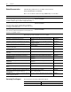
Summary of Changes Manual Updates This information summarizes the changes to the DriveLogix5730 Controller for PowerFlex 700S Drives with Phase II Control, publication 20D-UM003, since the July 2004 release. Change Added information for contacting Technical Support and updated Controller Firmware Revision information Updated information and example for specifying task priorities Updated information on controller fault response settings See Page...
soc-2
Table of Contents Important User Information . . . . . . . . . . . . . . . . . . . . . . . . . . . . . . . . . . . . . . . . . . . . . . . 1-2 Summary of Changes Manual Updates . . . . . . . . . . . . . . . . . . . . . . . . . . . . . . . . . . . . . . . . . . . . . . . . . . . . . . . . . i-1 Preface Overview Who Should Use This Manual . . . . . . . . . . . . . . . . . . . . . . . . . . . . . . . . . . . . . . . . . . . . . Purpose of this Manual . . . . . . . . . . . . . . . . . . . . . . . . . . . .
ii Chapter 4 Configuring DriveLogix Motion De-energizing the Drive to Connect or Disconnect a Cable . . . . . . . . . . . . . . . . . . . . . . . 4-1 About this Chapter. . . . . . . . . . . . . . . . . . . . . . . . . . . . . . . . . . . . . . . . . . . . . . . . . . . . . . . 4-1 System Requirements . . . . . . . . . . . . . . . . . . . . . . . . . . . . . . . . . . . . . . . . . . . . . . . . . . . . 4-1 Programming the Controller . . . . . . . . . . . . . . . . . . . . . . . . . . . . . . . . . . . . .
iii Chapter 9 Communicating with Devices on a DH485 Link De-energizing the Drive to Connect or Disconnect a Cable . . . . . . . . . . . . . . . . . . . . . . . Understanding How the DriveLogix5730 Controller Supports DH485 Communications Configuring Your System for a DH-485 Link. . . . . . . . . . . . . . . . . . . . . . . . . . . . . . . . . . Planning a DH-485 Network. . . . . . . . . . . . . . . . . . . . . . . . . . . . . . . . . . . . . . . . . . . . . . . Installing a DH-485 Network . . . . . . . .
iv
Preface Overview Who Should Use This Manual This manual is intended for qualified personnel. You must be able to program and operate Adjustable Frequency AC Drive devices and programmable controllers. Purpose of this Manual This manual guides the development of projects for DriveLogix controllers.
p-2 Overview Related Documentation Allen-Bradley publications are available on the internet at www.rockwellautomation.com/literature. These core documents address the Logix5000 family of controllers: If you are: a new user of a Logix5000 controller Use this publication: Logix5000 Controllers Quick Start publication 1756-QS001 This quick start provides a visual, step-by-step overview of the basic steps you need to complete to get your controller configured and running.
Overview Controller Firmware Revision p-3 This revision on the DriveLogix 5730 User Manual corresponds to the following: • Version 15.04 and later controller firmware • Version 15.xx and later RSLogix 5000 programming software • Version 3.02 and later DriveExecutive programming software General Precautions Class 1 LED Product ! ! ! ! ATTENTION: Hazard of permanent eye damage exists when using optical transmission equipment. This product emits intense light and invisible radiation.
p-4 Notes: Overview
Chapter 1 What is DriveLogix5730? The DriveLogix controller is part of the Logix environment. The DriveLogix controller provides a distributed control system built on these components: • The DriveLogix5730 controller has one RS-232 port. The controller supports the Logix instructions. • RSLogix 5000 programming software that supports every Logix controller. • Direct connection to host PowerFlex 700S drive. • Compact I/O modules that provide a compact, DIN-rail or panel mounted I/O system.
1-2 What is DriveLogix5730? Loading Controller Firmware De-energizing the Drive to Connect or Disconnect a Cable ! ATTENTION: Severe injury or death can result from electrical shock or burn. Verify that the voltage on the bus capacitors has discharged before connecting to the communication ports. Measure the DC bus voltage at the +DC & -DC terminals on the Power Terminal Block. The voltage must be zero.
What is DriveLogix5730? 1-3 The controller’s EtherNet/IP configuration settings are maintained during a flash process. If you load firmware via an EtherNet/IP connection, browse through the network port, across the virtual backplane, and select the appropriate controller. Using ControlFlash to load firmware You can use ControlFlash to load firmware through either an Ethernet connection (an IP address must already be assigned to the Ethernet port) or a serial connection. 1.
1-4 What is DriveLogix5730? Using AutoFlash to load firmware You can use AutoFlash to load firmware through either an Ethernet connection (an IP address must already be assigned to the Ethernet port) or a serial connection. 1. Make sure the appropriate network connection is made before starting. 2. Use RSLogix 5000 programming software to download a controller project. If the processor firmware does not match that project revision, AutoFlash automatically launches. 3.
What is DriveLogix5730? Using CompactFlash 1-5 The 1784-CF64 CompactFlash card provides nonvolatile memory storage for the DriveLogix5730 controller. The card stores the contents of the controller memory (program logic and tag values) and the controller firmware at the time that you store the project. Storing information to the CompactFlash card is like storing a snapshot of controller memory at a given time.
1-6 What is DriveLogix5730? Developing Programs The controller operating system is a preemptive multitasking system that is IEC 1131-3 compliant.
What is DriveLogix5730? 1-7 Specifying task priorities Each task in the controller has a priority level. The operating system uses the priority level to determine which task to execute when multiple tasks are triggered. You can configure periodic tasks to execute from the lowest priority of 15 up to the highest priority of 1. A higher priority task will interrupt any lower priority task. The continuous task has the lowest priority and is always interrupted by a periodic task.
1-8 What is DriveLogix5730? The following example shows the task execution order for an application with two periodic tasks and one continuous task.
What is DriveLogix5730? 1-9 Defining routines A routine is a set of logic instructions in a single programming language, such as ladder logic. Routines provide the executable code for the project in a controller. A routine is similar to a program file or subroutine in a PLC or SLC controller. Each program has a main routine. This is the first routine to execute when the controller triggers the associated task and calls the associated program.
1-10 What is DriveLogix5730? The controller performs system overhead functions for up to 1 ms at a time. If the controller completes the overhead functions in less than 1 ms, it resumes the continuous task. As the system overhead percentage increases, time allocated to executing the continuous task decreases. If there are no communications for the controller to manage, the controller uses the communications time to execute the continuous task.
What is DriveLogix5730? 1-11 The interruption of a periodic task increases the elapsed time (clock time) between the execution of system overhead, as shown below. 1 ms 1 ms 1 ms 1 ms 1ms periodic task 1 ms 1 ms system overhead 9 ms of continuous task time 9 ms of continuous task time continuous task 0 5 10 15 20 25 elapsed time (ms) If you increase the time slice to 20%, the system overhead interrupts the continuous task every 4 ms (of continuous task time).
1-12 What is DriveLogix5730? Understanding the Virtual Backplane The DriveLogix5730 system has a five-slot virtual backplane. The controller, drive and other components occupy different assigned slots on the backplane.
Chapter 2 Placing and Configuring the Drive De-energizing the Drive to Connect or Disconnect a Cable ! ATTENTION: Severe injury or death can result from electrical shock or burn. Verify that the voltage on the bus capacitors has discharged before connecting to the communication ports. Measure the DC bus voltage at the +DC & -DC terminals on the Power Terminal Block. The voltage must be zero.
2-2 Placing and Configuring the Drive and must be present. If the associated links are not present, or are deleted, the communication connection between the controller and drive will be lost. The user-defined tags are made up of a fixed number of REAL (floating point) and DINT (double integer) data types. Links are not required within the drive’s firmware to support these tags.
Placing and Configuring the Drive 2-3 Placing and Configuring the When you create a project for the DriveLogix controller in RSLogix 5000, the Controller Organizer automatically displays the local DIN rail for Drive Compact I/O. You must add the PowerFlex 700S drive to the configuration, in a manner similar to adding an I/O module. The Controller Organizer automatically places the drive in slot two. In the Controller Organizer, select the I/O Configuration folder.
2-4 Placing and Configuring the Drive Select the Major Revision. 4. Configure the drive. Use the module properties wizard to specify characteristics for the module. Click Next to continue through the wizard. 5. Name the drive and specify the Comm Format. Click finish when you are done. The completed module appears in the Controller Organizer. ahw0774.tif ahw0773.tif 3. The selection you make for the Comm Format determines the communication format for the connection to the drive.
Placing and Configuring the Drive 2-5 Revision ahw0776.tif You must enter the correct drive VPL firmware revision, in order to launch DriveExecutive and create the appropriate links for the selected communication format. Determine the firmware revision by viewing parameter 314 [VPL Firmware Rev] in the drive. Communication Formats The communication format determines the data structure, tag names, and required links for communication to the drive.
Placing and Configuring the Drive Speed Control format. The tag structure for this example’s drive connection has the tag name of “drive_module”. ahw0778.tif 2-6 The following tables show the tag names and their relationship to parameters in the drive. These examples use a module name of “drive_module”. Table 2.
Placing and Configuring the Drive Table 2.
2-8 Placing and Configuring the Drive Table 2.
Placing and Configuring the Drive Table 2.
2-10 Placing and Configuring the Drive Table 2.
Placing and Configuring the Drive Inhibiting the Drive Connection 2-11 RSLogix 5000 programming software allows you to inhibit the controller’s connection to the drive, in the same way you inhibit its connection to an I/O module. Inhibiting the drive module shuts down the connection from the controller to the drive. When you create the module you can choose to inhibit it. After you have created the module you can inhibit or un-inhibit it by manipulating its properties window.
2-12 Placing and Configuring the Drive ahw0514.tif inhibit or 0 to uninhibit). Use a SSV instruction to write the Mode attribute back to the module. For example: Using DriveExecutive Lite If not already done, enter the drive firmware revision. Click the Finish button to apply the revision data. ahw0779.tif 1. In order to launch DriveExecutive Lite from within RSLogix 5000, the drives power rating must be selected. The drive firmware revision must be applied prior to selecting the power rating.
Placing and Configuring the Drive In the Controller Organizer, select the PowerFlex 700S drive. Right-click the drive module and select Properties. 3. Select the Power tab. 4. Select the correct Drive Rating. This data can be found on the PowerFlex 700S data nameplate. ahw0781.tif ahw0780.tif 2. 2-13 TIP: If your drive’s power rating does not appear as a selection, you do not have the DriveExecutive Lite database file for your drive.
2-14 Placing and Configuring the Drive Once the power rating is selected, apply your changes by selecting the Apply button. 6. Select the Setup tab. 7. Enter the file name for your DriveExecutive Lite parameter file, then click the Apply button. 8. Click the DriveExecutive button to launch DriveExecutive Lite. ahw0785.tif ahw0782.tif ahw0784.tif 5.
Placing and Configuring the Drive When asked to create a new DriveExecutive Lite file, select yes. ahw0786.tif DriveExecutive will then launch and open the newly created file ahw0787.tif 9.
2-16 Placing and Configuring the Drive Viewing the Communication Interface to the Controller DriveExecutive Lite has a setup screen that details the communication interface between the controller and drive. From this screen, the relationship between drive parameters and controller tags is presented for the selected communication format. You can create additional links within the drive for use with the user-defined tags in the controller.
Placing and Configuring the Drive ahw0790.tif To send additional data from the drive to the controller, go to the To DriveLogix tab. Click the button in front of the UserDefinedRealData[0] tag ahw0791.tif 2. 2-17 3. Select the desired source (parameter 307 [Output Voltage] in this example) in the resulting window.
2-18 Placing and Configuring the Drive Cnfg] configures the drive’s response to a general connection failure as detected by the drive. Parameter 388 [Lgx Closed Cnfg] configures the drive’s response to the controller closing the connection. All of these parameters configure the drive’s response to these exception events in the following ways: ignore, alarm, fault and coast to stop, fault and ramp to stop, fault and stop in current limit.
Placing and Configuring the Drive 2-19 Using Existing DriveExecutive Lite Files Before using an existing DriveExecutive Lite file, verify the firmware revision, communication format, and power rating in the drive file match the data entered in drive module properties in your DriveLogix application. Select Properties from the Drive menu. ahw0793.tif 2. View the revision and ratings on the General tab of the Properties window. ahw0794.tif 1. 3.
2-20 Placing and Configuring the Drive In RSLogix 5000, go to the Setup tab of the Properties window. Click the Browse button. Select the existing DriveExecutive file (Existing Drive.dno in this example). Click the open button. ahw0795.tif ahw0785.tif 4. ahw0796.tif Click the Apply button and then launch DriveExecutive. ahw0797.tif 5.
Placing and Configuring the Drive Accessing Drive Data 2-21 Drive data is displayed as structures of multiple tags. The names and data structures are based on the selected communication format. The programming software automatically creates the necessary structures and tags when you configure the drive module. Each tag name follows this format: ModuleName:Type.MemberName.SubMemberName.
2-22 Placing and Configuring the Drive ahw0798.tif Configuring the Controller’s You can configure the drive module to generate a major fault in the Response to a Connection controller if the drive loses its connection to the controller. Failure Check this box to configure the drive module to generate a major fault if it loses its connection to the controller If you do not configure the major fault to occur, you should monitor the drive module status.
Placing and Configuring the Drive 2-23 Monitoring the drive module Each communication format provides a drive status word that will indicate when a drive fault or alarm occurs. To view this data through the programming software: In the Controller Organizer, select Controller Tags. Right-click on the selected icon and select Monitor Tags. ahw0799.tif 1. Expand the data as necessary. ahw0800.tif 2.
Placing and Configuring the Drive You can write logic to monitor these bits and take appropriate action if a fault or alarm occurs. For example, you may want a drive alarm to turn on a warning lamp and a drive fault to sound an alarm and set the motor brake. Example: Energizing Alarm Lamp, Siren and Brake in Response to Fault and Alarm Status Bits ahw0801.tif Given this configuration, the following logic checks the fault and alarm drive status bits. ahw0802.
Placing and Configuring the Drive Recommended Programming Techniques Naming Tags Use a convention when naming tags and consistently follow it.
2-26 Placing and Configuring the Drive Use Aliasing for all Communication Format Connections Between DriveLogix and the PowerFlex 700S Using aliases for the tags in the Communication Format (i.e. Speed Control, Motion Control, Position Control, User-Defined 1 and User-Defined 2) has the following benefits: • Improves program portability over processors and through upgrades to DriveLogix, PowerFlex 700S, and RSLogix 5000 firmware.
Chapter 3 Placing and Configuring Local I/O De-energizing the Drive to Connect or Disconnect a Cable ! ATTENTION: Severe injury or death can result from electrical shock or burn. Verify that the voltage on the bus capacitors has discharged before connecting to the communication ports. Measure the DC bus voltage at the +DC & -DC terminals on the Power Terminal Block. The voltage must be zero.
Placing and Configuring Local I/O Refer to the Compact I/O Selection Guide, publication 1769-SG001, for information about selecting Compact I/O modules. Use the 20D-DL2-CR3 or 20D-DL2-CL3 cables to connect a DriveLogix5730 controller to a bank of Compact I/O. Use 1769-CRR1/-CRR3 or 1769-CRL1/-CRL3 expansion cable to connect banks of I/O modules. You can split a bank right after the power supply or after any I/O module. Each bank must contain one power supply.
Placing and Configuring Local I/O 3-3 20D-DL2-CL3 ahw0808.eps ahw0806.eps A 1769-CRL1/-CRL3 connects the left side of one bank of Compact I/O to the right side of another. This facilitates a horizontal I/O orientation. 1769-CRLX 1769-CRLX 20D-DL2-CR3 ahw0809.eps ahw0807.eps A 1769-CLL1/-CLL3 connects the left side of one bank of Compact I/O to the left side of another. A 1769-CRR1/-CRR3 connects the right side of one bank of Compact I/O to the right side of another.
3-4 Placing and Configuring Local I/O Estimating RPI As you install modules, the minimum backplane RPI increases. The RPI (request packet interval) defines the frequency at which the controller sends and receives all I/O data on the backplane. There is one RPI for the entire 1769 backplane. Consider these guidelines when installing modules: Type of Module: Considerations: digital and analog (any mix) • 1-4 modules can be scanned in 1.0 ms • 5-16 modules can be scanned in 1.
Placing and Configuring Local I/O Configuring the CompactBus In the Controller Organizer, select CompactBus Local icon. Right click and select Properties. ahw0810.tif ahw0811.tif 1. When you create a DriveLogix5730 project, the programming software automatically creates the local CompactBus. You must configure the CompactBus.
Placing and Configuring Local I/O On the General tab, specify the size of the chassis. Enter the number of modules you plan to install. Include the DriveLogix5730 controller and drive in this total, along with a maximum of 16 I/O modules, not including the power supply. The Comm Format for the CompactBus is automatically set to Rack Optimized and cannot be changed. Using the Connection tab, you can specify the RPI for the systems and choose to inhibit or uninhibit the CompactBus. ahw0812.
Placing and Configuring Local I/O Configuring Local I/O Modules Use your programming software to configure the I/O modules for the controller. In the Controller Organizer, select CompactBus Local icon. Right click and select New Module. 2. Select the new module (1769-IA16 in this example). ahw0815.tif ahw0813.tif ahw0814.tif 1. 3. Configure the module, using the module wizard to specify characteristics. Click Next to advance the wizard. Click Finish when you are done.
Placing and Configuring Local I/O Communication Formats The communication format determines the data structure the I/O module uses. Each format supports a different data structure. Presently, the DriveLogix5730 controller supports two data formats: • Input Data – INT (for 1769 input modules) • Data – INT (for 1769 output modules) TIP: The DriveLogix5730 controller must own its local I/O modules. No other Logix-based controller can own the local Compact I/O.
Placing and Configuring Local I/O 3-9 disconnected from the system bus while under power. All outputs turn off when the system bus or any module faults. RSLogix 5000 software creates tags for modules when you add them to the I/O configuration. The 1769 module tags define configuration (C) data type members which may include attributes for alternate outputs. DriveLogix5730 does not enable local modules to use the alternate outputs.
Placing and Configuring Local I/O On the Connection tab of the Module Properties dialog, you can select to inhibit that specific module. ahw0817.tif 3-10 TIP: To easily inhibit all local I/O modules, you can inhibit the CompactBus, which in turn inhibits all the modules on that bus. See Configuring the CompactBus on page 3-5. When you select to inhibit a module, the controller organizer displays a yellow circle symbol over the module.
Placing and Configuring Local I/O 3-11 inhibit or 0 to uninhibit). Use a SSV instruction to write the Mode attribute back to the module. For example: The GSV instruction gets the current status of the module named “input_module.” The SSV instruction sets the state of “input_module” as either inhibited or uninhibited. GSV ladder.tif When on, inhibits the module. When off, uninhibits the module.
3-12 Placing and Configuring Local I/O Configuring the Controller’s Response to a Connection Failure In a DriveLogix5730 system, the controller’s response to a CompactBus connection failure is dependant on the setting of the individual compact I/O modules. ahw0817.tif Important: The controller’s response to a connection failure of any I/O module is dependant on the configuration of the I/O modules.
Placing and Configuring Local I/O 3-13 This address variable: Is: MemberName Specific data from the I/O module; depends on the type of data the module can store For example, Data and Fault are possible fields of data for an I/O module. Data is the common name for values that are sent to or received from I/O points. SubMemberName Specific data related to a MemberName.
3-14 Placing and Configuring Local I/O Sample tag names for this example: Location: Example Tag Name: input module in slot 1, LOCAL Bank 1 Local:1:C Local:1:I output module in slot 2, LOCAL Bank 1 Local:2:C Local:2:I Local:2:O analog input module in slot 3, LOCAL Bank 2 Local:3:C Local:3:I analog output module in slot 4, LOCAL Bank 2 Local:4:C Local:4:I Local:4:O analog input module in slot 5, LOCAL Bank 2 Local:5:C Local:5:I Using aliases to simplify tag names An alias lets you create a tag t
Placing and Configuring Local I/O Monitoring I/O Modules 3-15 The DriveLogix5730 controller offers different levels at which you can monitor I/O modules. You can: • use the programming software to display fault data (See Displaying Fault Data on page 3-15) • program logic to monitor fault data so you can take appropriate action (Refer to Logix5000 Controllers Common Procedures Programming Manual, publication number 1756-PM001, for examples.
3-16 Placing and Configuring Local I/O The display for the fault data defaults to decimal. Change it to Hex to read the fault code. fault_word.eps If the module faults, but the connection to the controller remains open, the controller tags database displays the fault value 16#0E01_0001.
Placing and Configuring Local I/O 3-17 End-cap Detection and Module Faults If a module that is not adjacent to an end cap experiences a fault and the connection to the controller is not broken, only the module enters the fault state. If a module that is adjacent to an end cap experiences a fault, the module will fault and the controller may fault. 2. In the Controller Organizer, select CompactBus Local icon. Right click and select New Module. Select the 1769-MODULE (Generic 1769 Module). ahw0820.
3-18 Placing and Configuring Local I/O ahw0821.tif 3.Configure the module, using the module wizard to specify characteristics. Click Next to advance the wizard. Click Finish when you are done. The completed module will appear in the Controller Organizer. The generic module requires you to specify more parameters of the module. Important: The values you enter for these parameters are device specific. See the documentation for the device to determine which values to enter.
Placing and Configuring Local I/O 3-19 Entering the Configuration Information for the Module Once you configure a module using the generic 1769-MODULE, you must enter the configuration information for the module into the tag database. The configuration information is downloaded to the module at program download, power up, and whenever a module is inhibited and then uninhibited. In the Controller Organizer, double-click on Controller Tags. 2.
3-20 Notes: Placing and Configuring Local I/O
Chapter 4 Configuring DriveLogix Motion De-energizing the Drive to Connect or Disconnect a Cable ! ATTENTION: Severe injury or death can result from electrical shock or burn. Verify that the voltage on the bus capacitors has discharged before connecting to the communication ports. Measure the DC bus voltage at the +DC & -DC terminals on the Power Terminal Block. The voltage must be zero.
4-2 Configuring DriveLogix Motion Programming the Controller In RSLogix 5000, create a new project. 1. From the File menu, select New. 2. In the New Controller dialog define the project: a. Use Revision 15 or higher. b. Enter a Name for the project (e.g., Motion_Drive). c. Click the OK button.
Configuring DriveLogix Motion 3. In the Controller Organizer: a. Right-click on the I/O Configuration folder. b. Select New Module from the menu. 4. In the Select Module dialog, click the plus sign (+) next to Drives to expand the selection.
4-4 Configuring DriveLogix Motion 5. Select the desired drive (PowerFlex 700S 2-400V in this example) and click the OK button. 6. In the Major Revision dialog: a. Select the Major Revision number and click the OK button. 7. Configure the Drive by specifying the characteristics of the module using the New Module dialog: a. Enter a name for the drive in the Name field (Drive_Axis in this example). a. Select Motion Control in the Comm Format box. b. Verify that the Open Module Properties box is checked. c.
Configuring DriveLogix Motion 4-5 8. On the Connections tab of the Modules Properties dialog: a. Change the value on the Requested Packet Interval (RPI) box to 3.0 ms. b. Click on the Associated Axis tab and click the New Axis button to assign a channel to Axis00. c. In the New Tag dialog, create a new tag structure for Axis00 by typing Axis00 in the Name field and clicking the OK button. d. On the Associated Axis tab, click the New Axis button to assign a channel to Axis01.
4-6 Configuring DriveLogix Motion e. In the New Tag dialog, create a new tag structure for Axis01 by typing Axis01 in the Name field and clicking the OK button. f. On the Associated Axis tab, click the drop-down arrow next to Channel 0 (Primary) and select Axis00. g. On the Associated Axis tab, click the drop-down arrow next to Channel 1 (Auxiliary) and select Axis01.
Configuring DriveLogix Motion 9. Click on the Power tab and select the proper Drive Rating. 10. Click the Apply button. 11. Click the OK button. 12. Create a new Motion Group. a. In the Controller Organizer, right-click on Motion Groups. b. Select New Motion Group from the menu.
4-8 Configuring DriveLogix Motion c. Enter a Name for the Motion Group (Grouped_Axis in this example). d. Verify that the Open MOTION_GROUP Configuration box is checked. e. Click on the OK button. 13. In the Motion Group Wizard dialog, move each axis from the Unassigned box to the Assigned box by clicking on the axis name and then clicking the Add button. 14. Click the Next button.
Configuring DriveLogix Motion 4-9 15. Finish creating the new Motion Group: a. Set the Coarse Update Period to 4ms for version 13.xx or lower, or to 2ms for version 15.xx or higher. This is the minimum time usable with DriveLogix motion. b. Set the Auto Tag Update to Enabled. c. Set the General Fault Type to Non Major Fault. d. Click the Finish button. 16. Configure Axis00. a. Right click on the axis you want to configure (Axis00 in this example). b. Select Properties in the menu.
4-10 Configuring DriveLogix Motion 17. On the General tab: a. Associate the module with the drive. Match the Module name with the drive’s name in the I/O Configuration. b. Set the Channel to the channel being used for the encoder. Channel 0 must be selected for the Servo axis and Channel 1 can be used only for feedback. 18.
Configuring DriveLogix Motion 4-11 19. On the Units tab, define the Position Units. In this example the Position Units are revs (revolutions). Position Units can be almost anything (e.g. degrees, radians, pallets, widgets etc.). 20. Define Average Velocity Timebase as the sample rate that is used for the Average Velocity tag in the controller tags. 21. On the Conversion tab, setup the Positioning Mode for Linear to Rotary. 22. The Conversion Constant is the number of feedback counts per Position Unit.
4-12 Configuring DriveLogix Motion 23. On the Dynamics tab, define the limits for speed, acceleration, and deceleration. Important: Do not exceed the system dynamics. 24. On the Homing tab, setup the Homing Mode, Position, Offset and Sequence values. Refer to the following tables. Mode Active - the desired homing sequence is selected by specifying whether a home limit switch and/or the encoder marker are used for this axis. Active homing sequences always use the trapezoidal velocity profile.
Configuring DriveLogix Motion Offset Type the desired offset (if any) in position units the axis is to move, upon completion of the homing sequence, to reach the home position. In most cases, this value will be zero. Sequence Select the event that will cause the Home Position to be set: Sequence Type Description Immediate Sets the Home Position to the present actual position, without motion. Switch Sets the Home Position when axis motion encounters a home limit switch.
4-14 Configuring DriveLogix Motion Launching DriveExecutive from RSLogix Next open the drive properties window and launch DriveExecutive drive programming software. ahw0869.tif 1.In the Controller Organizer, select the PowerFlex 700S drive. Right-click the drive module and select Properties ahw0870.tif That will launch the Module Properties Window for the drive. Click on the Setup tab.
Configuring DriveLogix Motion 2.Type the desired DriveExecutive filename or browse for an existing one. ahw0872.tif ahw0871.tif Then click Apply. 3.Click the Launch DriveExecutive button to launch DriveExecutive Lite.
4-16 Configuring DriveLogix Motion Configuring the Drive with DriveExecutive Software In DriveExecutive software, connect to the drive and access the Display DriveLogix dialog as shown below: ahw0824.tif 1.From the Drive Menu, select Display DriveLogix. ahw0825.tif 2.Click on the From DriveLogix tab. 3.Verify that the Communication Format is set to Motion Control. Click OK to apply and close the DriveLogix Setup Dialog.
5.Click on the Link Source tab. 6.Type or select the desired Source parameter. ahw0826.tif 4.On the Links view, double-click on the desired Sink parameter. 4-17 ahw0827.
4-18 Configuring DriveLogix Motion Create the links in the table below: Table 4.
4-19 ahw0829.tif Configuring DriveLogix Motion 8.Type the desired value. Make the parameter settings shown in the table below: Table 4.
4-20 Configuring DriveLogix Motion Downloading the Settings and Links to the Drive ahw0873.tif 1.From the Drive Menu, select Display Download. 2.Using the resulting windows and RSLinx navigate to the drive and download the settings and links. Additional Testing and Programming is Necessary The steps in this chapter provide the minimum settings required to begin testing DriveLogix motion. ! ATTENTION: Running the system without proper tuning can cause unstable and unpredictable operation.
Configuring DriveLogix Motion Supported Motion Commands 4-21 The following Logix Motion Instructions are supported by the DriveLogix controller: Motion State • • • • • MSO (Motion Servo On) MSF (Motion Servo Off) MASD (Motion Axis Shutdown) MASR (Motion Axis Shutdown Reset) MAFR (Motion Axis Fault Reset) Motion Move • • • • • • • • • • MAJ (Motion Axis Jog) MAM (Motion Axis Move) MAS (Motion Axis Stop) MAH (Motion Axis Home) MAG (Motion Axis Gearing) MCD (Motion Change Dynamics) MRP (Motion Redefine
4-22 Notes: Configuring DriveLogix Motion
Chapter 5 Communicating with Devices on a Serial Link De-energizing the Drive to Connect or Disconnect a Cable ! ATTENTION: Severe injury or death can result from electrical shock or burn. Verify that the voltage on the bus capacitors has discharged before connecting to the communication ports. Measure the DC bus voltage at the +DC & -DC terminals on the Power Terminal Block. The voltage must be zero.
Communicating with Devices on a Serial Link Configuring the Hardware The RS-232 port is an isolated serial port built-in to the front of the Main Control Board. Refer to Opening Door Over Power Structure and Main Control Board on page B-2. ahw0914.eps Serial Port To connect to the serial port: 1. Select the appropriate cable. The 1756-CP3 cable attaches the controller directly to the controller.
Communicating with Devices on a Serial Link Configuring the Serial Port of the Controller 1. In the Controller Organizer, select the Controller folder. Right-click the selected folder and select Properties. On the Serial tab, specify serial port characteristics. ahw0915.tif ahw0916.tif 2. Characteristic: Description (default is shown in bold): Mode Select System (for DF1 communication) or User mode (for ASCII communication). Baud rate Specifies the communication rate for the serial port.
5-4 3. Communicating with Devices on a Serial Link On the System Protocol tab, select the appropriate DF1 communication mode for point-to-point or master/slave communications. ahw0918.tif ahw0917.tif Or use the User Protocol tab to specify ASCII protocol to communicate to an ASCII device. Use this mode: For: See page: DF1 point-to-point communication between the controller and one other DF1-protocol-compatible device. This is the default system mode.
Communicating with Devices on a Serial Link 5-5 Configuring the Communication Driver Use RSLinx software to configure the serial communication driver. Select the “DF1” driver. 1. In the Communications menu, select the Configure Driver. Specify a name for the driver and click OK. 3. Specify the appropriate communication settings. ahw0483.tif ahw0484.tif 2. ahw0482.tif ahw0481.tif From the Available Driver Type list select the DF1 Driver, then click Configure.
5-6 Communicating with Devices on a Serial Link In the following example, a workstation directly connects to a DriveLogi5730 controller over a serial link. This is useful for downloading a controller project directly to the controller. ahw0919.eps Example 1: Workstation Directly Connected to a DriveLogix Controller Use RSLogix 5000 programming software to configure the controller’s serial port for the DF1 point-to-point (full-duplex) protocol.
Communicating with Devices on a Serial Link In the following example, a workstation remotely connects to a DriveLogix controller over s serial link. A modem is connected to the controller to provide remote access. ahw0920.
5-8 Communicating with Devices on a Serial Link Master/Slave Communication Methods A master station can communicate with a slave station in two ways: Name: This method: Benefits: standard communication mode Initiates polling packets to slave stations according to their position in the polling array(s). Polling packets are formed based on the contents of the normal poll array and the priority poll array. This communication method is most often used for point-to-multipoint configurations.
Communicating with Devices on a Serial Link 5-9 Configuring a DF1 Master Station This field: Description: Station address The station address for the serial port on the DF1 master. Enter a valid DF1 address (0-254). Address 255 is reserved for broadcast messages. The default is 0. Transmit retries Specifies the number of times a message is retried after the first attempt before being declared undeliverable. Enter a value 0-127. The default is 3.
5-10 Communicating with Devices on a Serial Link If you choose one of the standard polling modes The master station polls the slave stations in this order: 1. all stations that are active in the priority poll array 2. one station that is inactive in the priority poll array 3. the specified number (normal poll group size) of active stations in the normal poll array 4.
Communicating with Devices on a Serial Link 5-11 Connecting the ASCII Device to the Controller To connect the ASCII device to the serial port of the controller: 1. For the serial port of the ASCII device, determine which pins send signals and which pins receive signals. 2.
5-12 Communicating with Devices on a Serial Link Configuring User Mode This field: Description: Buffer size Specify the maximum size (in bytes) of the data array you plan to send and receive. The default is 82 bytes. Termination characters Specify the characters you will use to designate the end of a line. The default characters are ‘$r’ and ‘$FF’. Append characters Specify the characters you will append to the end of a line. The default characters are ‘$r’ and ‘$l’.
Chapter 6 Communicating with Devices on an EtherNet/IP Link De-energizing the Drive to Connect or Disconnect a Cable ! ATTENTION: Severe injury or death can result from electrical shock or burn. Verify that the voltage on the bus capacitors has discharged before connecting to the communication ports. Measure the DC bus voltage at the +DC & -DC terminals on the Power Terminal Block. The voltage must be zero.
6-2 Communicating with Devices on an EtherNet/IP Link Communicating Through the Embedded EtherNet/IP Option For the DriveLogix controller to operate on an Ethernet network, you need: • a workstation with an appropriate EtherNet/IP communication daughtercard • RSLinx software to configure the EtherNet/IP communication driver • RSLogix 5000 programming software (Version 13 or later) to configure the embedded EtherNet/IP option or NetLinx EtherNet/IP communication daughtercard as part of the DriveLogix syst
Communicating with Devices on an EtherNet/IP Link 6-3 Assigning Network Parameters with BOOTP/DHCP The EtherNet/IP Option board ships with BOOTP enabled. You must assign an IP address to the Ethernet port in order for the controller to communicate over an EtherNet/IP network.
In the Request History panel you see the hardware addresses of devices issuing BOOTP requests. Double-click on the hardware address of the device you want to configure. ahw0859.tif 5. The New Entry window appears with the device’s Ethernet Address (MAC). Enter the Ethernet address, IP address, subnet mask, and gateway. Click OK. Note: The selected controller will verify that the IP address that has been assigned in this dialog does not belong to another device on the network.
Communicating with Devices on an EtherNet/IP Link 6. 6-5 To permanently assign this configuration to the device, highlight the device and click on the Disable BOOTP/DHCP button. When power is recycled, the device uses the configuration you assigned and not issue a BOOTP request. ahw0885.tif Important: If you do not select the Disable BOOTP/DHCP button, on a power cycles and drive resets, the controller clears the current IP configuration and will again begin sending BOOTP requests.
6-6 Communicating with Devices on an EtherNet/IP Link Using RSLinx Software to Set the IP Address Via the Controller Serial Port You need RSLinx software version 2.41 or higher. 1. Make sure the controller that uses the IP address is installed and running. 2. Make a serial connection to the controller via the CH0 serial connector. You might also need to use RSLinx software to create a DF1 driver for the workstation. See Chapter 5 for more information. 3. Start RSLinx. Open the RSWho window.
Communicating with Devices on an EtherNet/IP Link Using RSLogix 5000 Software to Set the IP Address 1. 2. Create a new offline project, with the drive and any other necessary components. In the Controller Organizer, select the I/O Configuration folder. Right-click the selected folder and select New Module. Important: You must create an offline project and download it to the controller before going online. If the controller is already programmed, skip these first three steps.
6-8 Communicating with Devices on an EtherNet/IP Link 4. To go online with the controller in RSLogix 5000 programming software, select Who Active from the Communications menu. Then highlight the controller and click the Download button. ahw0880.tif ahw0879.tif If the controller is already programmed click Go Online instead.
Communicating with Devices on an EtherNet/IP Link ahw0881tif In the Controller Organizer, right click on the icon for the port and select Properties. 6. Select the Port Configuration tab and enter the proper data. Uncheck the Enable Bootp checkbox. Click Set, Apply and OK to make changes. ahw0883.tif 5.
6-10 Communicating with Devices on an EtherNet/IP Link Configuring the EtherNet/IP Communications Driver Important: EtherNet/IP only works within the local subnet and with EtherNet/IP devices (not Ethernet control products). To configure the AB_ETH Ethernet communication driver perform the following steps in RSLinx: From the Communications menu, select Configure Drivers. ahw0853.tif 2. Select EtherNet/IP Driver from the list of Available Driver Types. Then Click Add New. ahw0854.tif 3. ahw0855.
Communicating with Devices on an EtherNet/IP Link Select where the EtherNet/IP devices reside. The software locates valid IP addresses. ahw0856.tif 4. 6-11 ahw0857.tif Click OK. 5. The driver is now available and you can select the EtherNet/IP port in RSLogix 5000. Controller Connections Over EtherNet/IP A Logix system uses a connection to establish a communication link between two devices.
6-12 Communicating with Devices on an EtherNet/IP Link Connections are allocations of resources that provide more reliable communications between devices than unconnected messages. All EtherNet/IP connections are unscheduled. An unscheduled connection is a message transfer between controllers that is triggered by the requested packet interval (RPI) or the program (such as a MSG instruction). Unscheduled messaging lets you send and receive data when needed.
Communicating with Devices on an EtherNet/IP Link 6-13 Accessing Distributed I/O I/O information is presented as a structure of multiple fields, which depend on the specific features of the I/O module. The name of the structure is based on the location of the I/O module in the system. Each I/O tag is automatically created when you configure the I/O module through the programming software. Each tag name follows this format: Location:SlotNumber:Type.MemberName.SubMemberName.
6-14 Communicating with Devices on an EtherNet/IP Link Device: Example Tag Names (automatically created by the software): remote adapter “FLEX_io_adapter” FLEX_io_adapter:I FLEX_io_adapter:I.SlotStatusBits FLEX_io_adapter:I.Data FLEX_io_adapter:O FLEX_io_adapter:O.Data remote “input_module” in slot 0 rack-optimized connection FLEX_io_adapter:0:C FLEX_io_adapter:0:C.Config FLEX_io_adapter:0:C.DelayTime_0 FLEX_io_adapter:0:C.DelayTime_1 FLEX_io_adapter:0:C.DelayTime_2 FLEX_io_adapter:0:C.
Communicating with Devices on an EtherNet/IP Link 6-15 Adding a Remote Controller If you want to add the controller as a remote consumed controller to the I/O configuration, you first add the EtherNet/IP port and then the controller. ahw0888.tif To Add a Remote Controller Build the I/O Configuration in this Order 1. Add the remote EtherNet/IP port or bridge to the local EtherNet/IP port. 2. Add the remote controller to the remote EtherNet/IP port.
6-16 Communicating with Devices on an EtherNet/IP Link The producer and consumer must be configured correctly for the specified data to be shared. A produced tag in the producer must be specified exactly the same as a consumed tag in the consumer. If any produced/consumed tag between a producer and consumer is not specified correctly, none of the produced/consumed tags for that producer and consumer will be transferred.
Communicating with Devices on an EtherNet/IP Link 6-17 Producing a tag Produced data must be of DINT or REAL data type or a structure. You can use a user-defined structure to group BOOL, SINT, and INT data to be produced. To create a produced tag: 1. You must be programming offline. 2. In the controller organizer, double-click the Controller Tags folder and then click the Edit Tags tab. 3. Select the tag that you want to produce, or enter a new tag, and display the Tag Properties dialog box. 4.
6-18 Communicating with Devices on an EtherNet/IP Link Consuming a Tag A consumed tag represents data that is produced (broadcast) by one controller and received and stored by the consuming controller. To create a consumed tag: 1. You must be programming offline. 2. In the controller organizer, double-click the Controller Tags folder and then click the Edit Tags tab. 3. Select the tag that you want to consume, or enter a new tag, and display the Tag Properties dialog box. 4.
Communicating with Devices on an EtherNet/IP Link 6-19 Sending Messages The DriveLogix5730 controller can send MSG instructions to other controllers and devices over an EtherNet/IP link. Each MSG instruction requires you to specify a target and an address within the target. Important: Revision 15.xx of DriveLogix firmware adds more stringent range checks when reading to or writing from tags. Message packets are limited to 240 bytes.
6-20 Communicating with Devices on an EtherNet/IP Link Communicating with Another Logix-based Controller All Logix-based controllers can use MSG instructions to communicate with each other. The following examples show how to use tags in MSG instructions between Logix-based controllers.
Communicating with Devices on an EtherNet/IP Link Type of MSG Instruction: Supported Source File Types: Supported Destination File Types: DriveLogix5730 writes to PLC-2 In the DriveLogix5730 controller, select one of these data types: Use the PLC-2 compatibility file.
6-22 Communicating with Devices on an EtherNet/IP Link Mapping Addresses The programming software includes a PLC/SLC mapping tool which allows you to make an existing controller array tag in the local controller available to PLC-2, PLC-3, PLC-5, or SLC controllers. To map addresses: ahw0889.tif 1. From the Logic menu, select Map PLC/SLC Messages. 2.
Communicating with Devices on an EtherNet/IP Link Type of MSG Instruction: Example Source and Destination: PLC-5 reads from DriveLogix5730 source tag “array_1” SLC reads from DriveLogix5730 SLC 5/05 SLC 5/04 OS402 and above SLC 5/03 OS303 and above destination element N7:10 6-23 The PLC-5, PLC-3, and SLC controllers support logical ASCII addressing so you do not have to map a compatibility file for MSG instructions initiated by a PLC-5, PLC-3, or SLC controller.
6-24 Communicating with Devices on an EtherNet/IP Link Using a MSG Instruction to Send an Email The controller is an email client that uses a mail relay server to send email. The DriveLogix5730 controller can execute a generic CIP message that sends an email message to an SMTP mail relay server using the standard SMTP protocol. Some mail relay servers require a domain name be provided during the initial handshake of the SMTP session.
Communicating with Devices on an EtherNet/IP Link 6-25 Creating String Tags On the Edit tab of the Controller Tags window, create three tags: ahw0892.
Communicating with Devices on an EtherNet/IP Link To include “To:”, “From:”, and “Subject:” fields in the email, use symbols to separate each of these fields. The “To:” and “From”” fields are required; the “Subject:” field is optional. Use a second set of symbols after the last one of these fields you enter.
Communicating with Devices on an EtherNet/IP Link 6-27 Configuring the MSG Instruction that Identifies the Mail Relay Server On the Configuration tab of the Message Configuration, fill out the following fields: ahw0898.tif 1.
Communicating with Devices on an EtherNet/IP Link Configuring the MSG Instruction that Transmits the Email 1. On the Configuration tab of the Message Configuration, fill out the following fields: ahw0900.tif 6-28 In this field: Enter: Service Type Custom Service Code 4b Instance 1 Class 32f Attribute 0 Source Element the tag that contains the email text This tag is of the STRING data type you created to contain the email text. In this example, EmailText.
Communicating with Devices on an EtherNet/IP Link On the Communication tab of the Message Configuration, set the Path in the same manner as in the MSG that identifies the mail relay server. Click Apply. Click OK. ahw0901.tif 2. 6-29 Understanding Email Status Codes Examine the destination element of the email MSG to see whether the email was successfully delivered to the mail relay server. This indicates that the mail relay server placed the email message in a queue for delivery.
6-30 Communicating with Devices on an EtherNet/IP Link Error Code (hex): Extended-Error Code (hex): 0xFF 0x0100 Error returned by email server; check the Destination string for reason. The email message was not queued for delivery. 0x0101 SMTP mail server not configured. Attribute 5 was not set with a SMTP server address. 0x0102 “To:” address not specified. Attribute 1 was not set with a “To:” address AND there is not a “To:” field header in the email body. 0x0103 “From:” address not specified.
Communicating with Devices on an EtherNet/IP Link In the following example, one DriveLogix5730 controller controls distributed I/O through a 1794-AENT module. ahw0906.eps Example 1: DriveLogix5730 Controller and Distributed I/O 6-31 DriveLogix5730 controller (DriveLogix1) EtherNet/IP 1794-AENT with distributed I/O (Remote1) Controlling Distributed I/O This example has DriveLogix1 controlling the I/O connected to the remote 1794-AENT module.
6-32 Communicating with Devices on an EtherNet/IP Link Example 2: Controller to Controller In the following example, one EtherNet/IP DriveLogix5730 controller communicates with another EtherNet/IP DriveLogix5730 controller over EtherNet/IP. Each controller has its own local I/O. ahw0907.eps EtherNet/IP DriveLogix1 DriveLogix2 workstation Producing and Consuming Tags Produced data must be of DINT or REAL data type or an array or structure.
Communicating with Devices on an EtherNet/IP Link 6-33 ahw0912.eps ahw0909.eps ahw0910.eps ahw0908.eps ahw0911.
Communicating with Devices on an EtherNet/IP Link Each produced tags requires one connection for the producing controller and an additional connection for each consuming controller. Each consumed tag requires one connection. Sending a MSG instruction To send a MSG from DriveLogix1 to DriveLogix2: 1. For DriveLogix1, create a controller-scoped tag and select the MESSAGE data type. 2. Enter a MSG instruction. In this example logic, a message is sent when a specific condition is met.
Communicating with Devices on an EtherNet/IP Link 6-35 Total Connections Required by DriveLogix1 The following table calculates the connections used in this example.
6-36 Notes: Communicating with Devices on an EtherNet/IP Link
Chapter 7 Communicating with Devices on a ControlNet Link De-energizing the Drive to Connect or Disconnect a Cable ! ATTENTION: Severe injury or death can result from electrical shock or burn. Verify that the voltage on the bus capacitors has discharged before connecting to the communication ports. Measure the DC bus voltage at the +DC & -DC terminals on the Power Terminal Block. The voltage must be zero.
7-2 Communicating with Devices on a ControlNet Link sure it’s properly installed in the DriveLogix controller. Refer to Installing the Communications Daughtercard on page B-9. You’ll need to configure the communication daughtercard slot number to 1 in the RSLogix 5000 programming software. The DriveLogix controller uses slot 0 for the Communication Format with the local drive.
Communicating with Devices on a ControlNet Link 7-3 Configuring Your Daughtercard as Part of the System Use RSLogix 5000 programming software to map the 1788-CNx communication daughtercard as part of the DriveLogix5730 system. In the Controller Organizer, add the communication daughtercard to the I/O Configuration folder. 1. In the Controller Organizer, select the I/O Configuration folder. Right-click the selected folder and select New Module.
7-4 Communicating with Devices on a ControlNet Link Configuring Distributed I/O The DriveLogix5730 controller supports distributed I/O over a ControlNet link. Configuring I/O in a remote chassis is similar to configuring local I/O. You create the remote communication module and distributed I/O modules on the local ControlNet daughtercard. To communicate with distributed I/O modules, you add a remote adapter and I/O modules to the I/O Configuration folder of the controller. ahw0924.
Communicating with Devices on a ControlNet Link 7-5 Accessing Distributed I/O I/O information is presented as a structure of multiple fields, which depend on the specific features of the I/O module. The name of the structure is based on the location of the I/O module in the system. Each I/O tag is automatically created when you configure the I/O module through the programming software. Each tag name follows this format: Location:SlotNumber:Type.MemberName.SubMemberName.
7-6 Communicating with Devices on a ControlNet Link Device: Example Tag Names (automatically created by the software): remote adapter “FLEX_io_adapter” FLEX_io_adapter:I FLEX_io_adapter:I.SlotStatusBits FLEX_io_adapter:I.Data FLEX_io_adapter:O FLEX_io_adapter:O.Data remote “input_module” in slot 0 rack-optimized connection FLEX_io_adapter:0:C FLEX_io_adapter:0:C.Config FLEX_io_adapter:0:C.DelayTime_0 FLEX_io_adapter:0:C.DelayTime_1 FLEX_io_adapter:0:C.DelayTime_2 FLEX_io_adapter:0:C.
Communicating with Devices on a ControlNet Link Scheduling the ControlNet Network In the Network menu, select Online. ahw0929.tif 1. Use RSNetWorx software to schedule the ControlNet network. The controller project must already be downloaded from RSLogix 5000 programming software to the controller and the controller must be in Program or Remote Program mode. Survey the network. Enable Edits ahw0926.tif 2. In the Network menu, select Properties. ahw0930.tif 3.
In the Network menu, select Properties. ahw0930.tif 4. 5. Edit the parameters as desired. Click Apply. Click OK. In the File menu, select Save. ahw0931.tif 3. Communicating with Devices on a ControlNet Link ahw0927.
Communicating with Devices on a ControlNet Link Enter a name and path for the network configuration. ahw0928.tif ahw0932.tif 6. 7-9 7. Click OK to optimize and reschedule the connections. Sending Messages The DriveLogix5730 controller can send MSG instructions to other controllers over a ControlNet link. Each MSG instruction requires you to specify a target and an address within the target.
7-10 Communicating with Devices on a ControlNet Link firmware, the MSG instruction errors because the destination tag is not large enough. To correct this error, change the destination tag to a DINT data type. MSG instructions are unscheduled. The type of MSG determines whether or not it requires a connection. If the MSG instruction requires a connection, it opens the needed connection when it is executed.
Communicating with Devices on a ControlNet Link 7-11 Communicating with Another Logix-Based Controller All Logix-based controllers can use MSG instructions to communicate with each other. The following examples show how to use tags in MSG instructions between Logix-based controllers.
7-12 Communicating with Devices on a ControlNet Link Type of MSG Instruction: DriveLogix writes to PLC-2 Supported Source File Types: Supported Destination File Types: In the DriveLogix controller, select one of these data types: Use the PLC-2 compatibility file.
Communicating with Devices on a ControlNet Link 7-13 To map addresses: ahw0889.tif 1. From the Logic menu, select Map PLC/SLC Messages. 2. Specify this information: For: In this field: Specify: For example: PLC-3, PLC-5, and SLC controllers File Number Type the file number of the data table in the PLC/SLC controller. 10 Tag Name Type the array tag name the local controller uses to refer to the PLC/SLC data table address.
7-14 Communicating with Devices on a ControlNet Link Type of MSG Instruction: Example Source and Destination: PLC-5 reads from DriveLogix5730 source tag “array_1” SLC reads from DriveLogix5730 SLC 5/05 SLC 5/04 OS402 and above SLC 5/03 OS303 and above destination element N7:10 The PLC-5, PLC-3, and SLC controllers support logical ASCII addressing so you do not have to map a compatibility file for MSG instructions initiated by a PLC-5, PLC-3, or SLC controller.
Communicating with Devices on a ControlNet Link 7-15 Maximum Number of Produced and Consumed Tags The maximum number of produced/consumed tags that you can configure depends on the connection limits of the communication device that transfers the produced/consumed data. Each produced tag uses one connection for the tag and the first configured consumer of the tag. Each consumer thereafter uses an additional connection.
7-16 Communicating with Devices on a ControlNet Link Producing a Tag Produced data must be of DINT or REAL data type or an array or structure. You can use a user-defined structure to group BOOL, SINT, and INT data to be produced. To create a produced tag: 1. You must be programming offline. 2. In the controller organizer, double-click the Controller Tags folder and then click the Edit Tags tab. 3. Select the tag that you want to produce, or enter a new tag, and display the Tag Properties dialog box. 4.
Communicating with Devices on a ControlNet Link 7-17 1. You must be programming offline. 2. In the controller organizer, double-click the Controller Tags folder and then click the Edit Tags tab. 3. Select the tag that you want to consume, or enter a new tag, and display the Tag Properties dialog box. 4. Specify: In this field: Type or select: Tag Type Select Consumed. Controller Select the name of the other controller.
7-18 Communicating with Devices on a ControlNet Link Determining the API The API (actual packets per interval) is related to the RPI for the connection and the NUT of the network.
Communicating with Devices on a ControlNet Link 7-19 Example 1: Total Connections Required by DriveLogix1 The following table calculates the connections used in this example.
Communicating with Devices on a ControlNet Link 3. Configure the MSG instruction. On the Configuration tab: For this item: Specify: Message Type CIP Data Table Read or CIP Data Table Write Source Tag Tag containing the data to be transferred Number of Elements Number of array elements to transfer Destination Tag Tag to which the data will be transferred 4. On the Communication tab, specify the communication path. A communication path requires pairs of numbers.
Communicating with Devices on a ControlNet Link 7-21 ahw0912.eps ahw0909.eps ahw0910.eps ahw0908.eps ahw0935.
7-22 Communicating with Devices on a ControlNet Link Each produced tags requires one connection for the producing controller and an additional connection for each consuming controller. Each consumed tag requires one connection. Example 2: Total connections required by DriveLogix1 The following table calculates the connections used in this example.
Communicating with Devices on a ControlNet Link 7-23 Example 3: Sending MSG Instructions You configure a MSG instruction to a Logix5550 controller the same as you do for a DriveLogix controller. All Logix-based controllers follow the same MSG configuration requirements. See Example 2 above. Configuring a MSG instruction for a PLC-5 controller depends on the originating controller.
7-24 Communicating with Devices on a ControlNet Link ahw0936.eps Producing and consuming tags with a ControlNet PLC-5 controller depends on the type of data. ControlNet DriveLogix5730 Controller (DriveLogix1) tagA ControlLogix Controller (Control1) DINT ControlNet PLC5 Controller (PLC5C1) DriveLogix5730 Controller (DriveLogix2) Producing a Tag to a ControlNet PLC-5 controller To produce a tag that a ControlNet PLC-5 controller can consume: 1.
Communicating with Devices on a ControlNet Link 7-25 The ControlNet PLC-5 controller stores floating-point data, which requires 32-bits regardless of the type of controller, as follows: – The first integer contains the upper (left-most) bits of the value. – The second integer contains the lower (right-most) bits of the value. To re-construct the floating point data within the ControlNet PLC-5 controller, first reverse the order of the integers and then copy them to a floating-point file.
7-26 Communicating with Devices on a ControlNet Link Example 3: Total Connections Required by DriveLogix1 The following table calculates the connections used in this example.
Chapter 8 Communicating with Devices on a DeviceNet Link De-energizing the Drive to Connect or Disconnect a Cable ! ATTENTION: Severe injury or death can result from electrical shock or burn. Verify that the voltage on the bus capacitors has discharged before connecting to the communication ports. Measure the DC bus voltage at the +DC & -DC terminals on the Power Terminal Block. The voltage must be zero.
8-2 Communicating with Devices on a DeviceNet Link For the DriveLogix controller to operate on a DeviceNet link, you need: • a workstation with an appropriate DeviceNet interface card • RSLinx software to configure the DeviceNet communication driver • RSLogix 5000 programming software (Version 13 or later) to configure the DeviceNet communication daughtercard or local 1769-SDN DeviceNet scanner module as part of the DriveLogix system • a NetLinx DeviceNet communication daughtercard installed on the DriveL
Communicating with Devices on a DeviceNet Link 8-3 Configuring the 1769-ADN Adapter In RSNetWorx for DeviceNet, select Online from the Network menu. Choose the appropriate driver depending on whether the computer is directly connected to DeviceNet or you are accessing the network through a controller’s backplane and using a different port. ahw0945.tif 1.
Communicating with Devices on a DeviceNet Link The software then prompts you to either upload or download. Choose upload. RSNetWorx will then browse the network and obtain their settings. ahw0946.tif 2. 3. Right click on the 1769-ADN and choose Properties. ahw0947.tif 8-4 4. Click on the I/O Bank 1 Configuration tab, then choose upload when prompted. The actual 1769-ADN I/O layout appears.
Communicating with Devices on a DeviceNet Link 8-5 TIP: Configuration changes made to the adapter or any of its I/O modules with RSNetWorx will not be saved or downloaded to the adapter once the adapter is configured in a scanner’s scanlist. To make configuration changes, the controller must be placed into the Program mode and the adapter must be temporarily removed from the scanner’s scanlist. Setting Up the 1788-DNBO DeviceNet Scanner Scanlist Right click on the 1788-DNBO and choose Properties.
8-6 Click on the adapter, then click on the single arrow pointing to the right. This moves the adapter from Available Devices to the scanner’s scanlist. ahw0951.tif ahw0950.tif Then click on the Edit I/O Parameters button 4. Verify that the Input Size and Output Size are correct. The Output and Input sizes correspond to the total number of output and input bytes noted from the adapter’s summary page.
Communicating with Devices on a DeviceNet Link 8-7 Mapping starts at word 0 for both the input and the output data image. The input status and output configuration words are no longer included with the I/O data scanlist. Use the status and configuration tags created in RSLogix 5000 software to read status or set configuration bits. TIP: The input and output data being exchanged by the scanner and adapter is packed data.
Communicating with Devices on a DeviceNet Link Module Command Array The module command array is the primary control interface between your control program and the module. In RSLogix 5000 software, the CommandRegister tag structure is as follows: ahw0953.tif 8-8 Output Word Bit Description Behavior 0 0 Run This bit controls when the module scans its mapped slave devices. When set (1), the scanner will process I/O data as defined by its scanlist.
Communicating with Devices on a DeviceNet Link Creating a Project for the DriveLogix5730 Controller 2. Select the 1788-DNBO DeviceNet Scanner from the list of possible communication devices. Click OK. ahw0940.tif ahw0939.tif In the Controller Organizer, select the I/O Configuration folder. Right-click the selected folder and select New Module. ahw0941.tif 1. 3. Enter a Name for the port and make sure it is assigned to slot 4. Click Finish.
8-10 Communicating with Devices on a DeviceNet Link If you are using a 1769-SDN Scanner Module, add it to the local CompactBus: ahw0942.tif In the Controller Organizer, select the I/O Configuration folder. Right-click the selected Local CompactBus and select New Module. Select the 1769-SDN DeviceNet Scanner from the list of possible communication devices. Click OK. ahw0943.tif 2. ahw0944.tif 1. 3. Enter a Name for the port and make sure it is assigned to appropriate I/O slot. Click Finish.
Communicating with Devices on a DeviceNet Link 8-11 All tags for I/O modules are automatically created when the profiles for these modules are configured. Double click on Controller Tags in the controller organizer to view these tags. Each I/O module slot has Input, Output and Configuration tags created, if they apply.
Communicating with Devices on a DeviceNet Link Entering Program Logic The program for this example consists of a single rung that is used to place the scanner into the RUN mode. ahw0955.
Chapter 9 Communicating with Devices on a DH485 Link De-energizing the Drive to Connect or Disconnect a Cable ! ATTENTION: Severe injury or death can result from electrical shock or burn. Verify that the voltage on the bus capacitors has discharged before connecting to the communication ports. Measure the DC bus voltage at the +DC & -DC terminals on the Power Terminal Block. The voltage must be zero.
9-2 Communicating with Devices on a DH485 Link Configuring Your System for For the DriveLogix5730 controller to operate on a DH-485 network, you need: a DH-485 Link a 1761-NET-AIC interface converter for each DriveLogix5730 controller you want to put on the DH-485 network. You can have two controllers per one 1761-NET-AIC converter, but you need a different cable for each controller. Connect one controller to port 1 (9-pin connector) and one controller to port 2 (mini-DIN connector).
Communicating with Devices on a DH485 Link 9-3 The cable you use to connect the controller depends on the port you use on the 1761-NET-AIC converter. If you connect to this port: Use this cable: port 1 DB-9 RS-232, DTE connection 1747-CP3 or 1761-CBL-AC00 port 2 mini-DIN 8 RS-232 connection 1761-CBL-AP00 or 1761-CBL-PM02 Step 2: Configure the DH-485 port of the controller 1. In RSLogix 5000 programming software, select the Controller folder. Right-click to select Properties. 2.
9-4 Communicating with Devices on a DH485 Link Specify these characteristics on the Serial Port tab (default values are shown in bold): Characteristic: Description (default is shown in bold): Baud Rate Specifies the communication rate for the DH-485 port. All devices on the same DH-485 network must be configured for the same baud rate. Select 9600 or 19200 Kbps. Node Address Specifies the node address of the DriveLogix controller on the DH-485 network. Select a number 1-31 decimal, inclusive.
Communicating with Devices on a DH485 Link 9-5 The allowable range of the node address of an initiator is 0 to 31. The allowable address range for all responders is 1 to 31. There must be at least one initiator on the network. Network Initialization The network requires at least one initiator to initialize it. Network initialization begins when an initiator on the network detects a period of inactivity that exceeds the time of a link dead timeout.
9-6 Communicating with Devices on a DH485 Link Installing a DH-485 Network A DH-485 network consists of a number of cable segments daisy-chained together. The total length of the cable segments cannot exceed 1219 m (4000 ft). Important: Use shielded, twisted-pair cable - either Belden 3106A or Belden 9842. A daisy-chained network is recommended. Star connections are not recommended ahw0606.
Communicating with Devices on a DH485 Link Connections Using Belden 3106 Cable The table and schematic diagram below shows wire/terminal connections for Belden 3106A cable. 6 5 4 3 2 1 OR/WH WH/OR BU ahw0604.
9-8 Communicating with Devices on a DH485 Link Grounding and Terminating a DH-485 Network You must terminate the network at the first and last PHYSICAL devices, by connecting pin 6 (Termination) to pin 5 (Data A). You must ground the network at the first PHYSICAL device by connecting pin 1 (Chassis Ground) to pin 2 (Shield). Add jumpers to connect pin 6 (Termination) to pin 5 (Data A) on the first and last PHYSICAL devices ahw0607.
Communicating with Devices on a DH485 Link 9-9 Browsing a DH-485 Network To improve performance when browsing a DH-485 network, configure the DH-485 network properties in RSLinx software to display only those nodes Remotely that actually exist on the network. 1. In RSLinx software, right-click on the DH-485 network you plan to browse and select Properties. 2. On the Browse Addresses tab, specify the lowest and highest addresses that exist on the DH-485 network. ahw0954.
9-10 Notes: Communicating with Devices on a DH485 Link
Appendix A DriveLogix5730 Controller Specifications DriveLogix5730 Controller Specifications Category serial port (CH0 -RS-232) Specification RS-232, fully isolated DF1, DH-485, ASCII 38.
A-2 DriveLogix5730 Controller Specifications DriveLogix5730 Certifications Certification c-UL-us CE(1) C-Tick(1) Pending at time of printing EtherNet/IP c-UL-us (1) Real-Time Clock Accuracy Description UL Listed for Class I, Division 2 Group A,B,C,D Hazardous Locations, certified for U.S. and Canada European Union 89/336/EEC EMC Directive, compliant with: • EN 50082-2; Industrial Immunity • EN 61326; Meas./Control/Lab.
DriveLogix5730 Controller Specifications A-3 Controller LEDs ! ATTENTION: The controller LEDs are only operational when the drive is energized, and only visible with the drive door open. Servicing energized equipment can be hazardous. Severe injury or death can result from electrical shock, burn or unintended actuation of controlled equipment. Follow Safety related practices of NFPA 70E, ELECTRICAL SAFETY FOR EMPLOYEE WORKPLACES.
A-4 DriveLogix5730 Controller Specifications Indicator: Color: Description: RUN off The controller is in Program or Test mode. FORCE BAT I/O COM OK solid green The controller is in Run mode. off No tags contain I/O force values. I/O forces are inactive (disabled). solid amber I/O forces are active (enabled). I/O force values may or may not exist. flashing amber One or more input or output addresses have been forced to an On or Off state, but the forces have not been enabled.
DriveLogix5730 Controller Specifications A-5 CompactFlash card LED ! ! ATTENTION: The CompactFlash LED is only operational when the drive is energized, and only visible with the drive door open. Servicing energized equipment can be hazardous. Severe injury or death can result from electrical shock, burn or unintended actuation of controlled equipment. Follow Safety related practices of NFPA 70E, ELECTRICAL SAFETY FOR EMPLOYEE WORKPLACES.
A-6 DriveLogix5730 Controller Specifications Embedded EtherNet/IP Option LEDs ! ATTENTION: The Embedded EtherNet/IP Option LEDs are only operational when the drive is energized, and only visible with the drive door open. Servicing energized equipment can be hazardous. Severe injury or death can result from electrical shock, burn or unintended actuation of controlled equipment. Follow Safety related practices of NFPA 70E, ELECTRICAL SAFETY FOR EMPLOYEE WORKPLACES.
DriveLogix5730 Controller Specifications Condition: Status: Indicates: Recommended Action: solid red held in reset The controller is holding the port in reset or the controller is faulted. Clear the controller fault. Replace the controller. self-test The port is performing its power-up self-test. Normal operation during power-up. No action required. major fault An unrecoverable fault has occurred. Cycle power to the controller. Replace the controller.
A-8 DriveLogix5730 Controller Specifications Battery Life Time ON/OFF at 25°C (77°F) at 40°C (104°F) at 60°C (140°F) Always OFF 14 months 12 months 9 months ON 8 hours per day 5 days per week 18 months 15 months 12 months ON 16 hours per day 5 days per week 26 months 22 months 16 months Always ON There is almost no drain on the battery when the controller is always ON. Battery duration after the LED turns on The battery indicator (BAT) warns you when the battery is low.
Appendix B Access Procedures Removing Power from Drive and Compact I/O ATTENTION: To avoid an electric shock hazard, verify that the voltage on the bus capacitors has discharged before performing any work on the drive. Measure the DC bus voltage at the +DC & –DC terminals of the Power Terminal Block. The voltage must be zero. ! Remove power before making or breaking cable connections. When you remove or insert a cable connector with power applied, an electrical arc may occur.
B-2 Access Procedures Opening Door Over Power Structure and Main Control Board ahw0966.eps Frames 1-4 Locate the slot in the upper left corner. Slide the locking tab up and swing the cover open. Special hinges allow cover to move away from drive and lay on top of adjacent drive (if present). Frame 5 Slide the locking tab up, loosen the right-hand cover screw and remove. Frame 6 Loosen 2 screws at bottom of drive cover. Carefully slide bottom cover down & out.
Access Procedures B-3 Removing the Outside Covers Task A B Description Loosen screws on face of front cover and remove the cover Loosen screws on side of rear cover and remove the cover Proper tightening torque for reassembly is 7-10 lb.-in. A ahw0751.eps esd.eps = B Removing the Inside Cover Proper tightening torque for reassembly is 7-10 lb.-in. A = A A ahw0863.eps A Description Loosen screws on face of front cover and remove the cover esd.
Access Procedures Connecting the Battery Allen-Bradley ships the DriveLogix controller with the battery installed, but disconnected. You must connect the battery while installing the drive. ahw0865.eps B-4 Battery Plug and socket Battery clip Storing the Battery ! ATTENTION: Store batteries in a cool, dry environment. We recommend 25° C with 40% to 60% relative humidity. You may store batteries for up to 30 days between -45° to 85° C, such as during transportation.
Access Procedures B-5 Replacing the Battery ! ! ATTENTION: Servicing energized equipment can be hazardous. Severe injury or death can result from electrical shock, burn or unintended actuation of controlled equipment. Follow Safety related practices of NFPA 70E, ELECTRICAL SAFETY FOR EMPLOYEE WORKPLACES. DO NOT work alone on energized equipment! ATTENTION: The controller uses a lithium battery, which contains potentially dangerous chemicals.
B-6 Access Procedures 12.On the front of the controller, is the BATTERY LED off? If: Then: Yes Go to the next step. No A. Check that the battery is correctly connected to the controller. B. If the BATTERY LED remains on, install another 1769-BA battery. C. If the BATTERY LED remains on after you complete Step B., contact your Rockwell Automation representative or local distributor. 13.Download the controller’s memory and program from the computer with RSLogix 5000 programming software. 14.
Access Procedures Installing the Embedded EtherNet/IP Option Board Task A B C D Description Install and tighten standoffs (7-10 lb.-in.) Align connector on Embedded EtherNet/IP Option Board with connector on Main Control Board Place Embedded EtherNet/IP Option Board on the Main Control Board Install and tighten screws (7-10 lb.-in.) B esd.eps = A D ahw0862.
B-8 Access Procedures Installing the Compact I/O Cable Task B C A D A B B C D E Description Remove screws Install clips on controller end of cable Plug controller end of cable into mating connector on the Logix Expansion Board Install and tighten screws (7-10 lb.-in.) Route and secure cable E = esd.eps E Use cable tie to anchor cable to slots on this flange for strain relief E E ahw0741.eps ahw0738.
Access Procedures B-9 Installing the Communications Daughtercard A B C C Description Align circuit board in Communications Daughtercard with rail on Daughtercard slot Insert the Communications Daughtercard C = esd.eps Task Tighten screws (7-10 lb.-in.) A A B ahw0867.eps Important: This procedure can be performed without removing the cassette, if the Logix Expansion Board is already installed.
B-10 Notes: Access Procedures
Appendix C Application Restrictions Additional Memory Requirements If you have this firmware revision (add all that apply): Revision 15.0 or later may require more memory than previous revisions (e.g., 10.x, 11.x). To estimate the additional memory that your project may require, use the following table: Then add the following memory requirements to your project: Increase per instance Component Which comes from this type of memory: I/O (base) Data and Logic (expansion) 15.
C-2 Application Restrictions Restriction: Description: In a Tag of a User-defined Data Type, an Instruction May Write Past the End of an Array. If you write too much data to an array that is within a user-defined data type, some instructions write beyond the array and into other members of the tag. Example 1: Instruction Stops at the End of the Array If the length is greater than the number of elements in the destination array . . . . . . then the instruction stops at the end of the array.
Application Restrictions C-3 When 1769 Compact I/O modules are used as local I/O modules in a Hold Last State and User-Defined Safe State Not DriveLogix5730 system, the local I/O modules do not support the Hold Last State or User-Defined Safe State features, even though you can configure Supported these options in the programming software.
C-4 Notes: Application Restrictions
Index Numerics 1769-ADN adapter 8-3 1769-CRL1/-CRL3 cable 3-2 1769-CRR1/-CRR3 cable 3-2 1788-DNBO DeviceNet scanner 8-5 20D-DL2-CL3 cable 3-2 20D-DL2-CR3 cable 3-2 A accessing distributed I/O on ControlNet 7-5 distributed I/O on EtherNetI/P 6-13 I/O data 3-12 Additional Memory Requirements C-1 addresses ControlNet communication to non-Logix controllers 7-12 aliases 3-14 certifications A-2 clock accuracy A-2 communicating master/slave serial methods 5-8 to non-Logix controller over ControlNet 7-11 communic
Index-2 connection failure configuring controller response to 3-12 ControlFlash 1-3 ControlNet accessing distributed I/O 7-5 communicating to non-Logix controllers 7-11 configuring communications driver 7-2 configuring system for 7-1 consuming tags 7-16 daughtercard 7-3 I/O 7-4 mapping addresses communication to non-Logix controllers 7-12 messages 7-9 producing and consuming data 7-14, 7-20, 7-23 producing tags 7-16 scheduling network 7-7 D daughtercard ControlNet 7-3 installing B-9 De-energizing the Driv
Index-3 I I/O accessing data 3-12 accessing distributed on ControlNet 7-5 accessing distributed on EtherNet/IP 6-13 configuring local 3-7 ControlNet 7-4 DeviceNet 8-2 direct connections 3-14 distributed over EtherNet/I/P 6-12, 6-31 end-cap detections 3-15 generic 1769-MODULE 3-17 hold last state 3-8 inhibiting 3-9 layout 3-3 max modules A-1 max number banks A-1 module faults 3-15 monitoring 3-15 placing 3-2 update 3-4 user-defined safe state 3-8 inhibiting I/O 3-9 the drive connection 2-11 installing Compa
Index-4 replacing battery B-5 routines defining 1-9 RPI 3-4, 3-6 RS-232 5-1 RSLinx configuring EtherNet/IP network parameters 6-6 RSLogix 5000 configuring network parameters 6-7 S scheduling ControlNet 7-7 serial link ASCII device 5-11 configuring communications driver 5-5 configuring serial port 5-3 configuring system for 5-1 DF1 point-to-point station 5-6 master 5-9 master station 5-9 master/slave 5-8 remote connection 5-7 slave 5-8 specifications A-1 specifications A-1 electrical A-1 environmental A-1
www.rockwellautomation.com Power, Control and Information Solutions Headquarters Americas: Rockwell Automation, 1201 South Second Street, Milwaukee, WI 53204-2496 USA,Tel: (1) 414.382.2000, Fax: (1) 414.382.
Allen-Bradley DriveLogix 5730 Controller User Manual