User Manual RFID Systems Bulletin Number 56RF
Important User Information Solid-state equipment has operational characteristics differing from those of electromechanical equipment. Safety Guidelines for the Application, Installation and Maintenance of Solid State Controls (publication SGI-1.1 available from your local Rockwell Automation® sales office or online at http://www.rockwellautomation.com/literature/) describes some important differences between solid-state equipment and hard-wired electromechanical devices.
Table of Contents Important User Information . . . . . . . . . . . . . . . . . . . . . . . . . . . . . . . . . . . . . . . . 2 Preface Who Should Use this Manual . . . . . . . . . . . . . . . . . . . . . . . . . . . . . . . . . . . . . . . 7 Purpose of this Manual . . . . . . . . . . . . . . . . . . . . . . . . . . . . . . . . . . . . . . . . . . . . . 7 Abbreviations. . . . . . . . . . . . . . . . . . . . . . . . . . . . . . . . . . . . . . . . . . . . . . . . . . . . . . 7 Additional Resources . . . . .
Table of Contents RSLogix 5000 Controller Tags Configuration Image Table and Tags. . . . . . . . . . . . . . . . . . . . . . . . . . . . . . . Input Image Table and Tags . . . . . . . . . . . . . . . . . . . . . . . . . . . . . . . . . . . . . . . Input Channel Tags . . . . . . . . . . . . . . . . . . . . . . . . . . . . . . . . . . . . . . . . . . . . . . Output Image Table and Tags . . . . . . . . . . . . . . . . . . . . . . . . . . . . . . . . . . . . . Output Channel Tags . . . . . . . . . . . . . . .
Table of Contents RFID Interface Block Web Page Home . . . . . . . . . . . . . . . . . . . . . . . . . . . . . . . . . . . . . . . . . . . . . . . . . . . . . . . . . . 125 Diagnostics . . . . . . . . . . . . . . . . . . . . . . . . . . . . . . . . . . . . . . . . . . . . . . . . . . . . . Network Settings. . . . . . . . . . . . . . . . . . . . . . . . . . . . . . . . . . . . . . . . . . . . . . . . EtherNet Statistics . . . . . . . . . . . . . . . . . . . . . . . . . . . . . . . . . . . . . . . . . . . .
Table of Contents Notes: 6 Rockwell Automation Publication 56RF-UM001A-EN-P - October 2011
Preface Read this preface to familiarize yourself with the rest of the manual. It provides information concerning: • who should use this manual • the purpose of this manual • related documentation • conventions used in this manual Who Should Use this Manual Use this manual if you are responsible for designing, installing, programming, or troubleshooting control systems that use the 56RF RFID products. You should have a basic understanding of electrical circuitry and familiarity with relay logic.
Preface MACID – Media Access Control Identification QD – Quick Disconnect RFID – Radio Frequency Identification SB – Sub-committee SINT – signed, single byte integer UID – Unique Identifier UUID – Universally Unique Identifier Additional Resources These documents contain additional information concerning related products from Rockwell Automation.
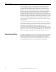
Chapter 1 Introduction What is RFID? RFID stands for Radio Frequency Identification. It is a method for communicating information from one point to another point by the use of electromagnetic waves (i.e., radio waves). It has unique characteristics that make it attractive for use in industrial systems. For example, you have a shipping carton that must be loaded with various goods to meet a customer’s specific purchase order. You can attach a tag to the carton.
Chapter 1 Introduction Power is coupled to the tag by an AC field produced in the transceiver. The powering field has a frequency of 13.56 MHz and is one of the industrial, scientific and medical (ISM) frequencies available for worldwide use. When sufficient power is received by the tag, it is able to respond to commands sent from the coupler.
Introduction The figure below shows a simple RFID system. This user manual describes the setup, installation, and programming required to get this system running. Figure 1 - RFID System MS 1783-US05T Ethernet/IP Switch NS LINK ETHERNET/IP L35E CompactLogix 1 56RF Transceiver P W R 2 3 Personal Computer 56RF Transceiver 4 5 Tracked Object 1783-US05T System Setup Chapter 1 56RF Interface Block 56RF Tag Tags are attached to objects that need to be tracked.
Chapter 1 Introduction Notes: 12 Rockwell Automation Publication 56RF-UM001A-EN-P - October 2011
Chapter 2 RFID Components This chapter covers the three key components that make up the RFID system: • the interface block • the transceiver • the tags Interface Block Three different interface blocks are available from which to choose. The table below shows the type of ports for each catalog number. Table 1 - Type of Ports Transceiver Ports Input Ports Output Ports Cat. No.
Chapter 2 RFID Components LED Indicators When the indicator is flashing, all flashes are 0.25 s ON and 0.25 s OFF. This block has the seven different indicators.
RFID Components LED Name LED State Aux Power RFID Port Transceivers Indicates Off There is no power or no IP address. Flashing red/ green Device in self-test Green The block is operating in a normal condition. Flashing green Standby. The device is not communicating with the interface block. Normal state when only power has been applied to the transceiver. Flashing red Connection timeout. Most often occurs when data is corrupted between interface block and transceiver. CRC failures etc.
Chapter 2 RFID Components Table 3 - LEDs LED Name Module Status Read/Write Status LED State Indicates Off There is no power applied to the block. Green The block is operating in a normal condition. Red The transceiver has an unrecoverable fault; may need replacing. Off There is no power applied to the device. Green The EIP interface block is communicating with the transceiver, but no tag is present. No errors received. Amber A tag is present within the antenna field.
RFID Components Chapter 2 Tag Memory Structure Universally Unique Identifier (UUID) Each tag has a different 64-bit hexadecimal UUID that is programmed during the production process according to ISO/IEC 15693-3 and cannot be changed afterwards. The numbering of the 64 bits is done according to ISO/IEC 15693-3 starting with the least significant bit (LSB) 1 and ending with the most significant bit (MSB) 64. This is in contrast to the general used bit numbering within a byte (starting with LSB 0).
Chapter 2 RFID Components Application Family Identifier (AFI) The AFI represents the type of application targeted. AFI is coded on one byte, which constitutes two nibbles of 4 bits each. The most significant nibble of AFI is used to code one specific or all application families, as defined in the table below. The least significant nibble of AFI is used to code one specific or all application sub-families. Sub-family codes different from 0 are proprietary.
RFID Components Chapter 2 Data Storage Format Identifier (DSFID) The DSFID indicates how data is structured in the tag memory. It may be programmed and locked by the respective commands. It is coded on one byte. It allows for instant knowledge on the logical organization of the data. Electronic Article Surveillance (EAS) EAS is a technology typically used to prevent shoplifting in retail establishments. An EAS detection system will detect active tags and set off an alarm.
Chapter 2 RFID Components SLI EAS Function The LSB of Byte 1 in Block -2 holds the EAS bit (Electronic Article Surveillance mode active – the label responds to an EAS command) Table 8 - EAS Block -2, Byte 1 MSB X LSB X X X X X X e EAS: e = 1 (EAS enabled) e = 0 (EAS disabled) IMPORTANT Changing of the EAS Configuration must be done in secure environment. The label must not be moved out of the communication field of the antenna during writing.
RFID Components Chapter 2 Write Access Conditions The Write Access Condition bits in block -1 determine the write access conditions for each of the 28 user blocks and the special data block. These bits can be set only to 1 with a lock command (and never be changed back to 0), i.e. already write protected blocks can never be written to from this moment on. In block -2 each byte can be individually locked.
Chapter 2 RFID Components Smart Label IC – Secure (SLI-S) The 2048 bit EEPROM memory is divided into 64 blocks. A block is the smallest access unit. Each block consists of 4 bytes (1 block = 32 bits). Four blocks are summed up to one page for password protection. Bit 0 in each byte represents the least significant bit (LSB) and bit 7 the most significant bit (MSB), respectively.
RFID Components Chapter 2 Smart Label IC – Lean (SLI-L) The SLI-L is used in applications that require smaller memory size. The 512 bit EEPROM memory is divided into 16 blocks. A block is the smallest access unit. Each block consists of 4 bytes (1 block = 32 bits). Four blocks are summed up to one page. Bit 0 in each byte represents the least significant bit (LSB) and bit 7 the most significant bit (MSB), respectively.
Chapter 2 RFID Components Ferroelectric Random Access Memory (FRAM) FRAM is a non-volatile memory that uses ferroelectric film as a capacitor for storing data. FRAM offers high speed access, high endurance in write mode, low power consumption, non-volatility, and excellent tamper resistance. The FRAM tags have 2000 bytes for use as user area and 48 bytes for use as system area. The FRAM tag memory areas consist of a total of 256 blocks (250 blocks of user area and 6 blocks of system area).
RFID Components Chapter 2 Table 16 - Structure of FCH to FFH MSB LSB FCH 3F 3E 3D 3C 3B 3A 39 03 02 01 00 FDH 7F 7E 7D 7C 7B 7A 79 43 42 41 40 FEH BF BE BD BC BB BA B9 83 82 81 80 FFH Reserved for future use (6 bits) F9 C3 C2 C1 C0 The security status of the user area is stored in the block security status bit in system area blocks of FCH…FFH per bit in each block.
Chapter 2 RFID Components Component Catalog Number Table The following tables show the catalog numbers for the components in the Bul. 56RF product family. EtherNet/IP Interface Blocks Transceiver Ports Input Ports Output Ports Cat. No. 1 1 1 56RF-IN-IPS12 2 1 1 56RF-IN-IPD22 2 2 0 56RF-IN-IPD22A Dimensions [mm] Recommended Sensing Distance [mm] ➊ Max. Sensing Distance [mm] ➊ Cat. No.
RFID Components Chapter 2 Accessories Transceiver Style Connector Type No. of Pins Shield Wire Size [AWG] Female straight to male straight DC Micro (M12) Patchcords DC Micro (M12) Cordsets M12 Terminal Chambers Female straight to male right angle Female right angle to male straight Cat. No.
Chapter 2 RFID Components EtherNet/IP Style Connector Type No. of Pins Shield Wire Size [AWG] Cat. No.
Chapter 3 Electrical Installation The EtherNet/IP switch must be mounted inside a control panel. The Bul. 56RF EIP interface block and Bul. 56RF transceivers can be mounted on the machine. Figure 6 - Transceiver Mounting Mounted in a Cabinet Mounted on the Machine 1 1 P W R 2 3 2 4 5 1783-US05T Cable Overview 3 1783-US05T Ethernet/IP Switch 56RF Interface Block 56RF Transceivers Three types of cables are needed. 1. This is an EtherNet cable, RJ45 to M12-QD patchcord. 2.
Chapter 3 Electrical Installation Auxiliary Power Connection Attach a micro-style 4-pin female to the micro-style 4-pin male receptacle as shown below. The female side is used to daisy chain the power to another device. The power connection is limited to 4 A. When the daisy chain approach is used, the maximum number of interface blocks that can be connected is determined by the total power consumed by each block. IMPORTANT Power must be connected to the male connector first.
Electrical Installation Power Connection Options Chapter 3 Each interface block is limited to 4 A total consumption. Example 1: Daisy Chain the Power Connections This example allows for a simple and easy way to distribute power to the RFID system. This approach is preferred when the total current of the RFID system is less than 4 A.
Chapter 3 Electrical Installation Transceiver Connection The M12 QD female connector for the transceivers is shown below. Pin 5 is the cable shield connection and is connected only at the block to functional earth (FE). 2 1 3 4 5 Pin Function 1 24V DC power 2 Data + 3 24V common 4 Data - 5 Shield/FE Digital Input Connection The female M12 QD input connector is shown below.
Electrical Installation Chapter 3 EtherNet I/P Connection The D-Code M12 connector on the interface block is shown in the figure below. 4 3 5 1 2 Pin Function 1 Tx+ 2 Rx+ 3 Tx- 4 Rx- 5 Connector shell connected to FE Use the Cat. No. 1585D-M4DC-H (polyamide small body unshielded) or the Cat. No. 1585D-M4DC-SH (zinc die-cast large body shielded) mating connectors for the D-Code M12 female network connector. Use two twisted pair Cat 5E UTP or STP cables.
Chapter 3 Electrical Installation Notes: 34 Rockwell Automation Publication 56RF-UM001A-EN-P - October 2011
Chapter 4 EtherNet/IP Addressing The star structure consists of a number of devices connected to central switch. When this topology is used, only one EtherNet connection can be made to the Bul. 56RF interface block – this connection is made to the Link 1 connector. The Link 2 connection must remain unused.
Chapter 4 EtherNet/IP Addressing Linear Topology The linear topology uses the embedded switching capability to form a daisychain style network that has a beginning and an end. Linear topology simplifies installation and reduces wiring and installation costs, but a break in the network disconnects all devices downstream from the break. When this topology is used, both EtherNet connections are used. The network connection to Link 1 or Link 2 does not matter.
EtherNet/IP Addressing Device Level Ring (DLR) Topology Chapter 4 A DLR network is a single-fault tolerant ring network intended for the interconnection of automation devices. DLR topology is advantageous as it can tolerate a break in the network. If a break is detected, the signals are sent out in both directions. When this topology is used, both EtherNet connections are used. The network connection to Link 1 or Link 2 does not matter.
Chapter 4 EtherNet/IP Addressing Setting the Network Address Before using the Bul. 56RF interface block in an EtherNet/IP network, configure it with an IP address, subnet mask, and optional Gateway address. This chapter describes these configuration requirements and the procedures for providing them. The address can be set in one of three ways: • Use the Network Address switches. • Use the Rockwell BootP/DHCP utility (version 2.3 or greater), which ships with RSLogix™ 5000. • Use RSLinx® software.
EtherNet/IP Addressing Advanced IP Addresses Chapter 4 The following steps show how to change the IP address from the fundamental 192.168.1.xxx to an advanced address. This assumes the Bul. 56RF interface block was already set up with an IP address using the network address switches. The examples below show the change process using specific addresses. The user is not limited to these addresses; the user can select any address that meets their needs. In the example below, we change from 192.168.1.
Chapter 4 EtherNet/IP Addressing Double-click on one of the EtherNet Address (MAC) of the device. The New Entry dialog appears showing the EtherNet Address (MAC) of the device. Type in the IP Address, Hostname and Description and click OK. The Hostname and Description are optional fields; they can be left blank. The device is added to the Relation List, displaying the EtherNet Address (MAC) and corresponding IP Address, Hostname, and Description. When the address is assigned to the Bul.
EtherNet/IP Addressing Chapter 4 5. Change the Network Adaptor to 192.168.2.1. Open the network connections of the host computer. Highlight the Internet Protocol (TCP/IP) connection. Click Properties. In the IP Address field, set the IP Address to 192.168.2.1. Click OK. Click Close to close the Local Area Connection window (this window must be closed to apply the new address). 6. Disable DHCP. Click on (only once) the interface block in the Relation List to highlight it. Then click Disable BOOTP/DHCP.
Chapter 4 EtherNet/IP Addressing Click File > Save As to save the relationship, if desired. Cycle the power to the Bul. 56RF interface block. You should no longer see the Bul. 56RF interface block appear in the Request History panel. From a DOS prompt, you can ping the new address. The response should be 4 packets sent, 4 packets received and 0 lost.
EtherNet/IP Addressing Chapter 4 The Configuration window appears. 1. Click on the Port Configuration tab. 2. Set the Network Configuration Type to Static (if not already done). 3. Change the IP Address to the new address. In this example, the address will be changed form 192.168.2.115 to 192.168.3.115. Click Yes to confirm the change. Click OK to close the configuration window. RSLinx places an X over the RFID adaptor because it can no longer communicate with it.
Chapter 4 EtherNet/IP Addressing Close and re-open the RSWho window. The older addresses are not available and the new addresses (192.168.3.115 and 192.168.3.214) appear. Note: If DHCP is not disabled, the Bul. 56RF interface block will show two requests in the DHCP Server at each power up. In the picture below, power was cycled to the Bul. 56RF interface block at 7:45:16, 7:47:47, 7:49:06 and again at 10:56:00. Each time power was applied, the Bul.
Chapter 5 Mechanical Installation Each of the transceivers has a similar but unique RF field that it generates. Fastening Attach the transceiver to the flat plate with M5 screws. The tightening torque must be 1.5 N•m for the M5 screw. Spacing Between Transceivers Installing more than one transceiver causes radio frequency interference and may result in the difficulty of the tag communication. Keep a sufficient distance between the transceivers as shown in Figure 12.
Chapter 5 Mechanical Installation Spacing Next to Metal Surfaces For the square transceiver, the communication distance will drop significantly when the distance between the transceiver and any surrounding metal is 30 mm (1.2 in.) or less. For the rectangular transceiver, the communication distance will drop significantly when the distance between the transceiver and any surrounding metal is 50 mm (2 in.) or less.
Mechanical Installation Chapter 5 Figure 14 - 65 x 65 mm Transceiver RFID Tag Alternate Direction of Travel 100 OFF Preferred Direction of Travel 50 Sensing Distance [mm] RFID Tag OFF Ideal Sensing Range ON Acceptable Sensing Range Side Lobe Side Lobe OFF 0 -80 -40 40 0 80 Misalignment (mm) Referenced for a 50 mm disc tag The field map for the 80 mm x 90 mm transceiver, shown in Figure 15, is very similar.
Chapter 5 Mechanical Installation Notes: 48 Rockwell Automation Publication 56RF-UM001A-EN-P - October 2011
Chapter 6 Add Your RFID Interface Block to an RSLogix 5000 Program 1. Open RSLogix 5000. 2. Click File>New. 3. Enter the new controller information. 4. Right click on the EtherNet port of the controller.
Chapter 6 Add Your RFID Interface Block to an RSLogix 5000 Program 5. Click New Module. 6. Select the desired 56RF module and click OK.
Add Your RFID Interface Block to an RSLogix 5000 Program General Tab Chapter 6 The general panel describes the device, its definition and its IP address. 1. Make the four changes shown below and click Apply. a. Enter a name for the module. In this example, the name is RFID_1. You may have multiple modules, so be sure to give it a brief but descriptive name. The name that you assign to the module appears in the Controller Organizer navigation pane.
Chapter 6 Add Your RFID Interface Block to an RSLogix 5000 Program EtherNet Address When the controller is offline, the EtherNet address can be set. The user has three options. 1. When a Private Network is used, click on the Private Network radio button. Enter a value for the last octet between 1…254. Be sure not to duplicate the address of an existing device. In preceding example, the address of the RFID block is 192.168.1.115. 2.
Add Your RFID Interface Block to an RSLogix 5000 Program Module Definition Chapter 6 The user should not have to make changes to the default values. If necessary, changes can be made by clicking the Change button. The user can change the Series, Revision, Electronic Keying, Connection and Data Format. Click the down arrow on the Data Format field and select SINT. Click OK to accept the changes (or Cancel to retain the original settings). Click Help for more info.
Chapter 6 Add Your RFID Interface Block to an RSLogix 5000 Program Module Info The Module Info tab contains read only data that is populated when the controller goes on-line (a program is downloaded to or uploaded from the controller). In the left panel, the AOP shows the vendor, product type, product code. Revision level, serial number, and product name. In the right panel, the AOP shows the fault status, internal state (i.e., Run mode), and whether the file is owned and Module Identity.
Add Your RFID Interface Block to an RSLogix 5000 Program Chapter 6 Internet Protocol Tab For the purposes of this user manual, the user is expected to use a Private Address, that is, and address of 192.168.1.xxx. This window is automatically populated with the data. Port Configuration Tab The Port Configuration fields should not need to be changed for the Quick Start process. These fields only become active when the controller is on line.
Chapter 6 Add Your RFID Interface Block to an RSLogix 5000 Program Click on the ellipsis (…) under the Port Diagnostics. A window pops up showing the communications taking place between the controller and the transceiver connected to the port.
Chapter 7 RSLogix 5000 Controller Tags During the module installation, the RFID_1 tags are automatically loaded as controller tags. This makes the tags available to all programs. In the Controller Organizer, click on the Controller Tags. Three categories of tags appear. The tag name is comprised of the module name followed by a: • “:C” for Configuration • “:I” for Input • “:O” for Output. Configuration Image Table and Tags Expand the RFID_1:C by clicking the “+” box.
Chapter 7 RSLogix 5000 Controller Tags • CRN – The Configuration Revision Number is used internally with RSLogix for configuration information. The user does not need to use this tag. • Pt00FaultMode – The Pt00FaultMode is used in conjunction with FaultValue to configure the state of output 0 when a communications fault occurs. A value of 0 means that, in the case of a communications fault, the value in FaultValue will be used (Off or On). A value of 1 means that the last state will be held.
RSLogix 5000 Controller Tags Input Image Table and Tags Chapter 7 Expand the RFID_1:I by clicking the “+” box. This shows the input image table, which has the following tags: • AuxPwrFault – The AuxPwrFault bit will indicate if there is no auxiliary power detected. A value of 0 indicates no fault, a value of 1 indicates a fault condition. • BlockFault – The Block Fault bit will indicate if any of the RFID channels or input/output points is in a fault condition.
Chapter 7 RSLogix 5000 Controller Tags • Pt00OpenWire – The Pt00OpenWire bit will indicate if the input point 1 has an open wire condition. A value of 0 indicates no fault, a value of 1 indicates a fault condition. Open wire detection can be enabled or disabled during configuration. • Pt00OutputFault – The Pt00OutputFault bit will indicate if the output point 0 has a fault condition. Output faults would be No Load and/or Short Circuit.
RSLogix 5000 Controller Tags Chapter 7 Table 17 - Allowable Commands Value 1 2 3 4 5 6 8 Command Read Single Block Read Multiple Blocks Multi-tag Block Read Read Byte Start Continuous Read Stop Continuous Read Teach Continuous Read 10 11 12 13 14 20 Write SingleBlock Write Multiple Blocks Multi-tag Block Write Clear Multiple Bytes Write Byte Inventory 31 33 34 Read Transceiver Settings Get Version Information Get System Information 40 41 42 43 44 45 Lock Block Write AFI Lock AFI Write DSFID Lock DS
Chapter 7 RSLogix 5000 Controller Tags • Reset – The channel reset bit will indicate the reset status of the RFID channel. A value of 0 indicates the channel is not in reset, a value of 1 indicates the channel has completed a reset. • ResetInProgress – The channel ResetInProg bit will indicate the status of an RFID channel reset. A value of 0 indicates that the RFID channel is not currently undergoing a reset; a value of 1 indicates a reset in progress on that channel.
RSLogix 5000 Controller Tags Chapter 7 • Address – The channel Address word is a 2-byte value that will contain the address or block value within the RFID tag that the command will execute on. • BlockSize – The channel BlockSize word is a 2-byte value that will store the expected Block Size for the tag. Valid values are 0, 4, or 8 bytes per block. A value of 0 will default to a Block Size of 4 bytes per block.
Chapter 7 RSLogix 5000 Controller Tags • Reset – The channel reset bit is used to command an RFID channel reset. A value of 0 indicates the channel is not being commanded to reset, a value of 1 indicates a request to reset the channel. • Timeout – This value determines how long the interface will wait for a command response from the transceiver before indicating a message time out. The default value is 0, which sets the timeout at 750 ms.
Chapter 8 Commands Summary This section provide a summary of the commands supported by the RFID transceiver. Detail of the commands can be found in Chapter 9. This guide assumes familiarity with RSLogix 5000. The *.ACD file should already be downloaded into the PLC and working properly. The table below assumes the following: • The user has set up the RSLogix5000 AOP with Data Format set to SINT. • The RFID tag has blocks that are only 4 bytes each. • The UUID is set to zero (unless specified).
Chapter 8 Commands Summary Write Multiple Blocks Writes multiple blocks of user data to an FRAM tag Write AFI Writes 1 byte of information into the Application Family Identifier (AFI) area contained within block -2 Lock AFI Locks the 1 byte of information for the AFI area, preventing it from being modified Write DSFID Writes 1 byte of information in the DSFID area Lock DSFID Locks the 1 byte of information for the DSFID area, preventing it from being modified Get System Information Returns the
Chapter 9 RSLogix 5000 Code Examples This chapter contains examples of routines that will run in RSLogix 5000. The examples are written for an RF transceiver connected to the “0” connector on the RF interface block. A momentary switch is connected to the Digital Input connector. The switch is used to enable the routine to allow the user to repeat the routine easily. In the examples, the RFID block is identified as “_RFID1” Main Routine A partial listing of the Main Routine is shown below.
Chapter 9 RSLogix 5000 Code Examples Example Command Routines - Overview Many of the example routines (not the Main Routine) use the same ladder logic. The ladder logic is explained below. Rung 0 Rung 0 initiates the routine. A sensor or momentary switch, connected to the input connection of the RFID interface block, senses that an object (with an RFID tag attached) is approaching and enables the execution of the read routine. The sensor is the XIC bit labeled _RFID_1:I:Pt00Data.
RSLogix 5000 Code Examples Chapter 9 Rung 2 Start – With the output channel properly initialized, the Start bit enables the rung to begin execution. EQU RFID_1:I:Command[0].Command =0 – When an output command is updated, the interface block returns that command back to the input command. If the input command is zero (it was set in Rung 1), then the EQU output goes HI and enables the subsequent MOV command. MOV x to RFID_1:O:Command[0].
Chapter 9 RSLogix 5000 Code Examples Clear Multiple Bytes The Clear Multiple Bytes command clears multiple bytes of user data in a RFID tag. The user can specify the number of bytes to clear and the address from which to begin. This is very similar to a “copy” command. It copies the value you specify in the output data image Data[0] location to the addresses you specify. Set the following values in the output image table: a. xx:O.Channel[0].Command = 13 b. xx:O.Channel[0].Address = starting address c.
RSLogix 5000 Code Examples Chapter 9 Example Results To demonstrate the results, the Read Byte command was executed on an RFID tag. The data in this tag was a simple list of numbers starting from 1. Note the counter is 31. The Clear Multiple Byte command is executed successfully as the ChError = 0 and all the data bytes are zero. The counter increments to 32. The tag is read again (command = 4) to confirm the clearing. Data bytes 2 through 4 are successfully set to 0.
Chapter 9 RSLogix 5000 Code Examples Get Multiple Block Security Status The Get Multiple Block Security Status command retrieves the security status of multiple blocks within a tag. It will also display the Universally Unique Identifier (UUID) of the RFID tag. Set the following values in the output image table: a. xx:O.Channel[0].Command = 45 b. xx:O.Channel[0].Address = the first block to read c. xx:O.Channel[0].Block = 0 d. xx:O.Channel[0].Data[0] = 0 e. xx:O.Channel[0].
RSLogix 5000 Code Examples Chapter 9 Example Results The figure below shows the security status for the first three blocks. Blocks 0 and 2 are locked. Block 1 is not locked. The following information will be displayed: • xx:I.Channel[0].Data[0-7] = UUID • xx:I.Channel[0].Data[8-9] = Security status of block x • xx:I.Channel[0].
Chapter 9 RSLogix 5000 Code Examples d. e. f. g. h. i. xx:O.Channel[0].Data[0] = 0 xx:O.Channel[0].Length = 0 xx:O.Channel[0].Reset = 0 xx:O.Channel[0].Timeout = 0 xx:O.Channel[0].UIDLow = 0 (or UIDLow) xx:O.Channel[0].UIDHi = 0 (or UIDHi) Unless a UUID is specified, this command will operate on the first tag in the field. Specify a UUID in xx:O.Channel[0].UIDLow and xx:O.Channel[0].UIDHi to perform the command on a specific tag.
RSLogix 5000 Code Examples Chapter 9 The tag being read was Cat. No. 56RRF-TG-30. This tag has 28 blocks. The maximum block number is 27, as the first block is 0. Each block has 4 bytes. The maximum byte number is 3, as the first byte is 0. The IC Ref is the last byte reported. Get Version Information The Get Version Information command will retrieve the firmware version information from the transceiver. Set the following values in the output image table: a. xx:O.Channel[0].Command = 33 b. xx:O.
Chapter 9 RSLogix 5000 Code Examples Example Routine In the example routine below, the initialization in Rung 1 sets the address, length data, the Data[0] value used to clear the fields and sets the command value to 0. Because the address, length and data[0] can only be 0, the source in the MOV instruction can be set to 0. The BlockSize, Reset, Timeout, UIDLow and UIDHi are set to 0 in the output image table. Example Results The results are stored in Data [0…3]. In this example, the version is “de20007”.
RSLogix 5000 Code Examples Inventory Chapter 9 The inventory command returns the UUID and DSFID information from the RFID tags in the field. This command can read up to a maximum of four tags. The more tags in the field, the more time the tags need to be in the field to complete the inventory command. By setting the output image fields to specific values, the Inventory command returns the following information: 1. Returns the number of tags in the field and the UUID of each tag.
Chapter 9 RSLogix 5000 Code Examples Example Routine In the example routine below, the initialization in Rung 1 sets the address, length data, the Data[0] value used to clear the fields and sets the command value to 0. The BlockSize, Reset, Timeout, UIDLow and UIDHi are set to 0 in the output image table. The example ladder diagram is initially set for Address =0, Length = 0 and Data[0] = 0. These values are then changed to get obtain example results for the three versions of the Inventory command.
RSLogix 5000 Code Examples Chapter 9 In example 2, the length was changed to 1. the Address = 0, Length = 1 and Data[0] = 0. Four RFID tags were in the RF field at the time the read command was executed. The controller tag values are shown below. The data shows the number of tags in the RF field, the DSFID and the UUID for each tag.
Chapter 9 RSLogix 5000 Code Examples In example 3, we get the tag information for only those tags the have a specific AFI. In this example the AFI is 57. Address = 1, Length = 1 and Data[0] = 57. Two of the four RFID tags that were present in the RF field at the time the read command was executed had AFI set to 57. The controller tag values are shown below. The data shows the number of tags in the RF field, the DSFID and the UUID for each of these tags.
RSLogix 5000 Code Examples Chapter 9 Example Routine In the example routine below, the initialization in Rung 1 sets the address, length, the Data[0, UIDLow and UIDHi values used to lock the AFI and sets the command value to 0. The BlockSize, Reset, and Timeout are set to 0 in the output image table. Example Results The following figure shows an example of results on the input image table. The Command is showing 42 and the ChError is showing 0. The input data bytes are all zero.
Chapter 9 RSLogix 5000 Code Examples Lock Block The Lock Block command locks one block of user data, preventing future writing. Once the block is locked, the block cannot be unlocked. The transceiver automatically determines the block size of the RFID tag. Set the following values in the output image table: a. xx:O.Channel[0].Command = 40 b. xx:O.Channel[0].Address = the number of the block to lock c. xx:O.Channel[0].BlockSize = 0 d. xx:O.Channel[0].Data[0] = 0 e. xx:O.Channel[0].Length = 0 f. xx:O.
RSLogix 5000 Code Examples Chapter 9 Example Results The output image table shows address 26. This is the second to last block of the Cat. No. 56RF-TG-30 tag. The command is 40. The UUID must be specified to lock any blocks. After completion of the lock block command, the input image table should show the command is 40 and the ChError is 0. Errors The ChErrorfield will show will be 8 if you try to lock a block that is already locked.
Chapter 9 RSLogix 5000 Code Examples Lock DSFID The Lock DSFID command will lock the 1 byte of information for the Data Storage Format Identifier (DSFID) area of the tag, preventing it from being modified.Once the DSFID byte is locked, it cannot be unlocked. Set the following values in the output image table: a. xx:O.Channel[0].Command = 44 b. xx:O.Channel[0].Address = 0 c. xx:O.Channel[0].Data[0] = 0 d. xx:O.Channel[0].Length = 0 e. xx:O.Channel[0].Reset = 0 f. xx:O.Channel[0].Timeout = 0 g. xx:O.
RSLogix 5000 Code Examples Chapter 9 Example Results When successful, the results shown in the input image table show ChError = 0 and the Command number =44. If you try to lock the DSFID on an RFID tag already locked, the ChError will be equal to 8. Read Byte Command The Read Byte command reads a user-specified number of bytes from a tag, starting at a user-specified address. An Option Flag can be set to return the UUID of the tag.
Chapter 9 RSLogix 5000 Code Examples Example Routine Below is example routine to read all the data and the UUID in a Cat. No. 56RFTG-30 ICODE tag. This tag holds a maximum of 112 bytes of data. In the example routine below, the initialization in Rung 1 sets the address, length, the Data[0]to the Option Flag, and sets the command value to 0. The BlockSize, Reset, Timeout, UIDLow, and UIDHi are set to 0 in the output image table.
RSLogix 5000 Code Examples Chapter 9 Example Results The following figure shows an example of results where the Option Flag was set to 1, which reads the UUID. The UUID is loaded into Data[0] through Data[7]. The user data (1, 2, 3, 4, 5, 6…) begins in Data[8]. The figure below only shows a partial listing of the user data. The command read in 112 bytes of data. In the figure below, the command was repeated with the Starting Address set to 2 and the number of bytes set to 3.
Chapter 9 RSLogix 5000 Code Examples Multi-Tag Block Read The Multi-Tag Block Read command reads multiple blocks of user data from multiple tags in the RF field. The transceiver automatically determines the block size. All RFID tags in the field should have the same block size. This command can read up to four tags. Adequate time must be allowed to read all the tags in the RF field. Set the following values in the output image table: a. xx:O.Channel[0].Command = 3 b. xx:O.Channel[0].
RSLogix 5000 Code Examples Chapter 9 Example Routine In the example routine below, the initialization in Rung 1 sets the address, length, the Data[0] value used to read multiple tags and sets the command value to 0. The BlockSize, Reset, Timeout, UIDLow, and UIDHi are set to 0 in the output image table. The example ladder diagram is initially set for Address =25 and the Length = 2. The command will read blocks 25 and 26.
Chapter 9 RSLogix 5000 Code Examples Example Results The input image data fields are populated with the number of tags, followed by the UUID and block data of each tag. In the example below, four Cat. No. 56RF-TG-30 RFID tags were read. These tags hold 4 bytes per block. Since two blocks (25 and 26) were read, a total of eight data fields are used to store the user data. The figure only shows the information from two of the four RFID tags.
RSLogix 5000 Code Examples Chapter 9 Unless a UUID is specified, this command will operate on the first tag in the field. Specify a UUID in xx:O.Channel[0].UIDLow and xx:O.Channel[0].UIDHi to perform the command on a specific tag. Example Routine In the example routine below, the initialization in Rung 1 sets the address, length, and Data[0] values used to read multiple blocks and sets the command value to 0. The BlockSize, Reset, Timeout, UIDLow and UIDHi are set to 0 in the output image table.
Chapter 9 RSLogix 5000 Code Examples Example Results This first example uses Option Flag = 0; return only the data in the blocks. With a starting block number of 25 and two blocks to read, data from Blocks 25 and 26 are returned. The tag was a Cat. No. 56RF-TG-30 which has only 4 bytes per block. The data appears in the input channel Data[0…7]. This second example shows the results for Option Flag = 1; return the data and the security status.
RSLogix 5000 Code Examples Chapter 9 Set the following values in the output image table: a. xx:O.Channel[0].Command = 1 b. xx:O.Channel[0].Address = the block number to read. c. xx.O.Channel[0].BlockSize = 0 d. xx:O.Channel[0].Data[0] = the Option Flag value e. xx:O.Channel[0].Length = 0 f. xx:O.Channel[0].Reset = 0 g. xx:O.Channel[0].Timeout = 0 h. xx:O.Channel[0].UIDLow = 0 (or UIDLow) i. xx:O.Channel[0].
Chapter 9 RSLogix 5000 Code Examples Example Results • Option Flag 0 —This first example uses Option Flag = 0; return only the data in the block. The block number is 26. The tag was a Cat. No. 56RFTG-30 which has only 4 bytes per block. The data appears in the input channel Data[0…3]. • Option Flag 1—The second example demonstrates the results when Option Flag = 1. Data[0] shows the security status of the block. The 1 indicates the block has been locked. A zero indicates the block is unlocked.
RSLogix 5000 Code Examples Chapter 9 Example Routine In the example routine below, the initialization in Rung 1 sets the address, length, data, and command. Because the address, length and Data[0] can only be 0, the source in the MOV instruction can be set to 0. The UIDLow, UIDHi, BlockSize, Reset and Timeout are set to 0 in the output image table. Example Results The following information will be displayed: • xx:I.Channel[0].Data[0…1] = Device ID • xx:I.Channel[0].Data[2…5] = Baud rate • xx:I.
Chapter 9 RSLogix 5000 Code Examples Write AFI The Write AFI command writes one byte of information into the Application Family Identifier (AFI).The AFI is used to group RFID tags by application. This allows the transceiver to read and write only to those tags with the specified AFI value. Set the following values in the output image table: 1. xx:O.Channel[0].Command = 41 2. xx:O.Channel[0].Address = 0 3. xx:O.Channel[0].BlockSize = 0 4. xx:O.Channel[0].Data[0] = AFI value 5. xx:O.Channel[0].
RSLogix 5000 Code Examples Chapter 9 Example Results The following figure shows an example of results on the input image table. The Command is showing 41 and theChError is showing 0. The data bytes are all zero. Confirmation that the AFI was written can be observed in the Get_System_Information_Routine. Write Byte Command The Write Byte command writes bytes of user data to a tag. The user must specify the data, the start byte, and the number of bytes to write. a. xx:O.Channel[0].Command = 14 b. xx:O.
Chapter 9 RSLogix 5000 Code Examples Example Routine In the example routine below, the initialization in Rung 1 sets the address, length, and Data[0] values used to read multiple blocks and sets the command value to 0. The BlockSize, Reset, Timeout, UIDLow and UIDHi are set to 0 in the output image table. The example ladder diagram is initially set for Address =0, the Length = 10. Data[0…9] are set to a sequential list of numbers starting with 11.
RSLogix 5000 Code Examples Chapter 9 After successful completion of the Write Byte command, the input image table shows the UUID of the tag. The Read_Byte_Routine can be used to read the data. The data is stored in the input channel data, starting at location 0. Write DSFID The Write DSFID (Data Storage Format Identifier)command will write one byte of information in the Data Storage Format Identifier (DSFID) of the RFID tag. Set the following values in the output image table: a. xx:O.Channel[0].
Chapter 9 RSLogix 5000 Code Examples Example Routine In the example routine below, the initialization in Rung 1 sets the address, length, and Data[0] values used to read multiple blocks and sets the command value to 0. The BlockSize, Reset, Timeout, UIDLow, and UIDHi are set to 0 in the output image table. The example ladder diagram is initially set for Address =0, the Length = 0. Data[0] is set to the DSFID value.
RSLogix 5000 Code Examples Write Multiple Blocks Chapter 9 The Write Multiple Blocks command writes to either one or two blocks of user data to a FRAM tag. This command will only work on FRAM tags. Cat. No. 56RF-TG-2KB is a FRAM tag. a. xx:O.Channel[0].Command = 11 b. xx:O.Channel[0].Address = starting block to write c. xx:O.Channel[0].BlockSize = number of bytes per block d. xx:O.Channel[0].Data[0…xxx] = data to write e. xx:O.Channel[0].Length =the number of blocks to write f. xx:O.Channel[0].
Chapter 9 RSLogix 5000 Code Examples Example Routine In the example routine below, the initialization in Rung 1 sets the address, length, and block size values used to write multiple blocks and sets the command value to 0. The BlockSize, Reset, Timeout, UIDLow, and UIDHi are set to 0 in the output image table. Example Results The figure below shows the output image table with the data that will be written (a simple numeric sequence starting at 2). Two blocks of 8 bytes each will be written to the tag.
RSLogix 5000 Code Examples Chapter 9 If the write multiple blocks command is executed properly, the input table image results shows ChError = 0, Command = 11 and Data[0-xxx] =0. Use the Read Multiple Block command (=2) to read the data. Multi-Tag Block Write The Write Multi-Tag Block command writes one or more blocks of user data to multiple tags in the transceiver field. The maximum number tags in the RF field is limited to four and all tags must have the same block size.
Chapter 9 RSLogix 5000 Code Examples If UIDLow and UIDHi are set to 0, this command will operate on the first tag in the field. Specify a UUID in xx:O.Channel[0].UIDLow and xx:O.Channel[0].UIDHi to perform the command on a specific tag. Note: Length must be in 4-byte increments (e.g., 4, 8, 12…) for ISO15693 tags or 8-byte increments (e.g., 8, 16, 24…) for FRAM tags. Note: The BlockSize field is used to specify the number of bytes/block of the tag.
RSLogix 5000 Code Examples Chapter 9 Example Results The input channel image table will show the number of RFID tags that were written and the UUID of each RFID tag. Use the Read Multi Tag Block command (=3) to read the blocks and confirm the data was written.
Chapter 9 RSLogix 5000 Code Examples Write Single Block The Write Single Block command writes a single block of user data to an RFID tag. Set the following values in the output image table: a. xx:O.Channel[0].Command = 10 b. xx:O.Channel[0].Address = starting address to write c. xx:O.Channel[0].BlockSize = 0, 4, or 8 d. xx:O.Channel[0].Data[0…112] = data to write e. xx:O.Channel[0].Length = 0, 4, or 8 f. xx:O.Channel[0].BlockSize = 0, 4, or 8 g. xx:O.Channel[0].Reset = 0 h. xx:O.Channel[0].Timeout = 0 i.
RSLogix 5000 Code Examples Chapter 9 Example Routine In the example below, 4 bytes of data will be written to Block 3. The data is loaded into the output channel image table. Block three will be populated with Data[0…3] = 41, 42, 43, and 44. Example Results The output image table shows that the address is set to Block 3; the block size is 4 and the command is 10. The data to be written to block 3 is 41, 42, 43, and 44.
Chapter 9 RSLogix 5000 Code Examples Upon successful completion of the write block command, the Input Image table shows that Command = 10 and ChError = 0. The input channel data fields are all zero. Use the Read Single Block command (=1) , with option flag set to zero, to read the contents of the tag in block 3. Continuous Read Mode The Continuous Read command is used for specialty applications requiring high line speeds (up to 3 m/s).
Chapter 10 SLC Code Examples This sample code is an example using a SLC-5/05 with a Cat. No. 56RFINIPD22 interface block. Read Byte Routine The Read Byte command (value =4) reads a user-specified number of bytes from a tag, starting at a user-specified address. Additionally, an Option Flag can be set to return the UUID of the tag.
Chapter 10 SLC Code Examples Example Routine Rung 0000: Place RFID interface into the Run mode. The bit should be highlighted in green. If the bit is not green, right-click it and click "Toggle Bit". Rung 0001: Read Input Image. Double-click the EEM box to enter the setup screen. Input Size is 116 bytes (58 words). Click on the MultiHop tab to set up an EtherNet/IP Device. Rung 0002: Write Output Image. Double-click the MSG box to enter the setup screen. Output size is 124 bytes (62 words).
SLC Code Examples Chapter 10 Rung 0004: When the command value has been cleared, load in the instruction parameters contained in N104 (Read Byte). N101 (Read Single Block) could be used in place of N104. Rung 0005: Wait for the read command to run. The Read in Progress bit will be highlighted in green when the command is running. When the command has completed, the Read in Progress bit will return to its original state. When the command has been executed and completed, copy the data read into N100.
Chapter 10 SLC Code Examples Notes: 112 Rockwell Automation Publication 56RF-UM001A-EN-P - October 2011
Chapter 11 MicroLogix 1400 Code Examples Read Byte The Read Byte command (value =4) reads a user-specified number of bytes from a tag, starting at a user-specified address. Additionally, an Option Flag can be set to return the UUID of the tag. • Option Flag 0 – Returns the specified user data • Option Flag 1 – Returns the UUID of the tag and the specified user data Note: This command operates only on the first tag in the field. Example Routine • Rung 0000: Place RFID interface into the Run Mode.
Chapter 11 MicroLogix 1400 Code Examples • Rung 0002: Write Output Image. Double-click the MSG box to enter the setup screen. Output size is 124 bytes (62 words). Click on the MultiHop tab to set up an EtherNet/IP Device. • Rung 0003: The Tag Present bit will be highlighted in green when a tag is present. When a tag is present, clear the command value. • Rung 0004: When the command value has been cleared, load in the instruction parameters contained in N104 (Read Byte).
MicroLogix 1400 Code Examples Write Byte Chapter 11 The Write Byte command (value = 14) writes bytes of user data to a tag. The user can specify the data, the start byte, and the number of bytes to write. Note: This command operates only on the first tag in the field. Example Routine • Rung 0000: Place RFID interface into the Run Mode. The bit should be highlighted in green. If the bit is not green, right-click it and click Toggle Bit. • Rung 0001: Read Input Image.
Chapter 11 MicroLogix 1400 Code Examples • Rung 0001: Read Input Image. Double-click the MSG box to enter the Setup Screen. Input Size is 116 bytes (58 Words.) Click on the MultiHop tab to set up an EtherNet/IP Device. • Rung 0002: Write Output Image. Double-click the MSG box to enter the Setup Screen. Output Size is 124 bytes (62 Words). Click on the MultiHop tab to set up an EtherNet/IP Device. • Rung 0003: The Tag Present bit will be highlighted in green when a tag is present.
MicroLogix 1400 Code Examples Chapter 11 Input Image Layout Refer to Appendix B (Class 4 Assembly Object) for details on the Input Image Layout. Output Image Layout Refer to Appendix B (Class 4 Assembly Object) for details on the Output Image Layout.
Chapter 11 MicroLogix 1400 Code Examples Notes: 118 Rockwell Automation Publication 56RF-UM001A-EN-P - October 2011
Chapter 12 RFID Tag Speed The tables below are to be used as a guide to help determine the amount of information that can be written to/read from an RFID tag based on the speed of your application. For example, in order to consistently read 8 bytes from a tag using the square transceiver, your line speed should be 0.827 m/s or slower. If you have a high speed application, it is best to choose the largest transceiver, larger tag, which will provide the largest antenna range.
Chapter 12 RFID Tag Speed Table 20 - M18 Transceiver Max Tag Speed (m/s) Bytes Read Write 4 0.1984127 0.1771479 8 0.1838235 0.1495886 16 0.1603849 0.1142204 32 0.1277139 0.07748935 64 0.09070295 0.04713646 112 0.06325111 0.02970444 160 0.04855547 0.02168492 2000 0.004899919 0.00191022 Table 21 - M30 Transceiver Max Tag Speed (m/s) Continuous Read Mode Bytes Read Write 4 0.3373016 0.3011515 8 0.3125 0.2543007 16 0.2726544 0.1941748 32 0.2171137 0.1317319 64 0.
RFID Tag Speed Chapter 12 When the interface receives a stop command, Command 6, it will revert back to the normal mode of operation and resume the polling cycle. Continuous Read mode can also be canceled by issuing a channel reset (reset bit in the output image word set to 1). When using a 50 mm disc tag, Cat. No. 56RF-TR-8090 transceiver, and reading 4 bytes of data it may be possible to achieve a line speed of up to 3 m/s.
Chapter 12 RFID Tag Speed Mode Overview 1. Mode 0 The interface waits for the delay time, sends out a read, obtains data, and returns that data back to the PLC. This cycle repeats until a Stop Continuous Read command is issued. 2. Mode 1 The interface waits for input point 0 to turn ON, waits for the delay timer to expire then sends out a read, obtains data, and returns that data back to the PLC. This cycle repeats until a Stop Continuous Read command is issued. 3.
RFID Tag Speed Chapter 12 UIDLow/UIDHigh – Can be used to target only a specific tag for read operations, otherwise this value would be 0 to read any tag. Mode x – Specifies the mode of operation for the Continuous Read. Option Flag – Used to specify the mode of the Read Multiple/ Read Single Block(s) command. A 0 value would only read the data requested starting at the address specified, for the number of blocks specified in the Length field.
Chapter 12 RFID Tag Speed recommended delay time value into the Timeout field prior to initiating a continuous read. During Teach Mode, the ContReadMode and Busy bit will be set to true. Teach mode can canceled by issuing a channel reset (reset bit in the output image word set to 1). Command Structure a. b. c. d. e. f. g. h. i. j. 124 xx:O.Channel[0].Reset =0 xx:O.Channel[0].BlockSize =Bytes per Block in the tag xx:O.Channel[0].Command = 8 xx:O.Channel[0].Address = Starting Block xx:O.Channel[0].
Chapter 13 RFID Interface Block Web Page The RFID interface block web page is accessible by entering the IP address of the interface block into a web browser. The interface block must have EtherNet connectivity and power to be viewable on the web page. The web page provides diagnostic and configuration for the RFID interface block. Home The Home page allows the user to view basic information about the interface block. Data cannot be changed on the home page.
Chapter 13 RFID Interface Block Web Page Diagnostics The Diagnostic section has three tabs of “view only” detailed information on the status of the interface block. The tabs show Diagnostic Overview, Network Settings, and EtherNet Statistics. The I/O Connections tab contains a field that allows the user to change the web page refresh rate.
RFID Interface Block Web Page Chapter 13 EtherNet Statistics I/O Connections Configuration To access the configuration section of the RFID interface block web page, a username and password are required. The default username is “Admin”, and there is no password by default. The username and password can be changed on the Device Services tab. Note: If the username and password are lost, the interface block must be reset to default before it can be accessed again.
Chapter 13 RFID Interface Block Web Page Device Identity Change the device name, description, or location. Changes will take place after the interface block has been power cycled.
Appendix A Error Codes for RFID Interface Block Error Codes The error codes for the RFID interface block are stored in the input for each channel. In the examples in the manual, the error codes are stored in the image table RFID_1:I:Channel[0].ChError and RFID_1:I:Channel[1].ChError.
Appendix A Error Codes for RFID Interface Block • Tag Communications Error (Decimal 8)– Indicates that the interface block was not able to complete execution of a command with a tag before the tag left the field or the Output Channel Timeout is set too short. For example, set the Output Channel Timeout to 100 ms and then try to read 112 byte of data from a Cat. No. 56RF-TG-30 tag. • Address Error (Decimal 9)– Indicates that the block address value was out of bounds for the tag.
Appendix B CIP Information Product Codes and Name Strings The following table lists the product codes and name strings for the EtherNet/IP interface block. Product Type 139 139 139 Product Code 4 5 6 Cat. No.
Appendix B CIP Information Identity Object Class Code 0x0001 This Identity Object provides identification of and general information about the device. Instance 1 of the Identity Object will contain the following attributes: Attribute ID 1 2 3 4 Access Rule Get Get Get Get 5 Get 6 7 Get Get Name Data Type Value Vendor Device Type Product Code Revision Major Revision Minor Revision Status UINT UINT UINT Structure of: USINT USINT WORD 1 139 4,5, or 6 The initial release is Major Rev.
CIP Information Appendix B CIP_Data[0]…[1]= Vendor (1=Allen-Bradley) CIP_Data[2]…[3]= Device Type (139=RFID) CIP_Data[4]…[5]=Device Code (5=56RF-IN-IPS12) CIP_Data[6]= Major Revision (1) CIP_Data[7]= Minor Revision (1) CIP_Data[8]…[9]= Status (100 decimal, 000000001100100 binary) CIP_Data[10]…[13]= Serial Number (A000B955) CIP_Data[14]= Product Name Length (32 bytes) CIP_Data[15]-[n]= Product Name Table 22 - Device Status (CIP_Data[8]…[9]) Bits 0 1 2 3 4…7 8 9 10 11 12…15 Name Owned Reserved Configured R
Appendix B CIP Information Assembly Object Class Code 0x0004 The Assembly Object binds attributes of multiple objects, which allows data to or from eachobject to be sent or received over a single connection. Controllers that do not have the ability to create and establish a class 1 (scheduled) connection can utilize the Assembly Object in a Message Instruction to obtain both the input and output assemblies of the RFID interface.
CIP Information Appendix B Reading the Input Image Table of a 56RF-IN-IPD22 with a MicroLogix 1400 • N10:0 is the data table address where the input image will be stored and will span N10:0 thru N10:57. • The number of bytes to receive is 116 (58 words). • The extended routing file (RIX11:0) is used to store the Multi-Hop routing information. • Service is type Read Assembly • Class 4 is the Assembly Instance Class • Instance 79h is the input image connection instance.
Appendix B CIP Information Input Image (56RF-IN-IPD22) Word N10:0 – N10:1 N10:2 N10:3 N10:4 N10:5 N10:6 N10:7 N10:8 Description Module Connection Status Module Status Reserved Block Status I/O Data Channel[0] Diagnostics Command Value Counter Value Word N10:9 N10:10 – N10:31 N10:32 N10:33 N10:34 N10:35 N10:36 – N10:57 Description Length Data Channel[1] Diagnostics Command Value Counter Value Length Data Module Status Bit 0 1 2 3 4 5 6 7 Definition Run Status Block Fault Aux Power Fault Reserved Pt00
CIP Information Appendix B Input Image (56RF-IN-IPD22A) Word N10:0 – N10:1 N10:2 N10:3 N10:4 N10:5 N10:6 N10:7 N10:8 Description Module Connection Status Module Status Reserved Block Status I/O Data Channel[0] Diagnostics Command Value Counter Value Word N10:9 N10:10 – N10:31 N10:32 N10:33 N10:34 N10:35 N10:36 – N10:57 Description Length Data Channel[1] Diagnostics Command Value Counter Value Length Data Module Status Bit 0 1 2 3 4 5 6 7 Definition Run Status Block Fault Aux Power Fault Reserved Pt00
Appendix B CIP Information Input Image (56RF-IN-IPS12) Word N10:0 – N10:1 N10:2 N10:3 N10:4 N10:5 Description Module Connection Status Module Status Reserved Block Status I/O Data Word N10:6 N10:7 N10:8 N10:9 N10:10 – N10:31 Description Channel[0] Diagnostics Command Value Counter Value Length Data Module Status Bit 0 1 2 3 4 5 6 7 Definition Run Status Block Fault Aux Power Fault Reserved Pt00 Input Fault Pt00 Open Wire Pt00 Input Short Circuit Reserved Bit 8 9 10 11 12 13 14 15 Definition Reserve
CIP Information Appendix B Writing to the Output Image Table of a 56RF-IN-IPD22 with a MicroLogix 1400 • N20:0 is the data table address to store the output image and will span N20:0…N20:61. • The number of bytes to send is 124 (62 words). • The extended routing file (RIX12:0) is used to store the Multi-Hop routing information. • Service is type Write Assembly • Class 4 is the Assembly Instance Class • Instance 83h is the output image connection instance.
Appendix B CIP Information Input Image (56RF-IN-IPD22) Word N20:0 N20:1 N20:2 N20:3 N20:4 N20:5 N20:6 N20:7 N20:8…N20:9 N20:10…N20:11 Description Module Data Reserved Channel[0] Reset Block Size Command Address Length Timeout UIDLow UIDHi Word N20:12…N10:31 N20:32 N20:33 N20:34 N20:35 N20:36 N20:37 N20:38…N20:39 N20:40…N20:41 N20:42…N20:61 Description Data Channel[1] Reset Block Size Command Address Length Timeout UIDLow UIDHi Data Module Data Bit 0 1 2 3 4 5 6 7 Definition Run Mode Reserved Reserved
CIP Information Appendix B Input Image (56RF-IN-IPS12) Word N20:0 N20:1 N20:2 N20:3 N20:4 N20:5 Description Module Data Reserved Channel[0] Reset Block Size Command Address Word N20:6 N20:7 N20:8…N20:9 N20:10…N20:11 N20:12…N10:31 Description Length Timeout UIDLow UIDHi Data Module Data Bit 0 1 2 3 4 5 6 7 Definition Run Mode Reserved Reserved Reserved Reserved Reserved Reserved Reserved Bit 8 9 10 11 12 13 14 15 Definition Pt00 Data Reserved Reserved Reserved Reserved Reserved Reserved Reserved Re
Appendix B CIP Information • N20:0 is the data table address to store the output image and will span N20:0…N20:61. • The Send Data size is 62 (124 bytes). • Service is type Write Assembly • Class 4 is the Assembly Instance Class • Instance 83h is the output image connection instance.
CIP Information Class 1 Connections Appendix B Class 1 connections are used to transfer I/O data, and can be established to the assembly object instances. Each Class 1 connection establishes two data transports, one consuming and one producing. The heartbeat instances are used for connections that shall access only inputs. Class 1 uses UDP transport.
Appendix B CIP Information Input Only Connection This connection is used to read data from the module without controlling the outputs. This connection is not dependent on any other connection. It is recommended that the originator sets the data size in the O->T direction of the Forward_Open be zero. IMPORTANT If an exclusive owner connection has been opened against the module and times out, the input only connection shall time-out as well.
CIP Information Discrete Input Point Object Class Code 0x0008 Appendix B The following class attributes are currently supported for the Discrete Input Point Object: Attribute ID 1 2 Access Rule Get Get Name Revision Max Instance Data Type 0xC7 UINT Value 2 4 Two instances of the Discrete Input Point Object are supported. All instances contain the following attributes.
Appendix B CIP Information Instance 1 is the first input (Pt00), if the RFID interface supports two inputs, then Pt01 would be instance 2. The return value in CIP_Data[0] will be either 0 (Input OFF) or 1 (Input ON). To obtain the Input Filter OffOn value of an input point, configure a CIP message as shown below: Instance 1 is the first input (Pt00), if the RFID interface supports two inputs, then Pt01 would be instance 2. The return value will contain the filter time in milliseconds.
CIP Information Appendix B The following common services are implemented for the Discrete Output Point Object.
Appendix B CIP Information Notes: 148 Rockwell Automation Publication 56RF-UM001A-EN-P - October 2011
Appendix C Install the AOP (Add-On Profile) Introduction This chapter goes through the add-on profile (AOP) of the RFID transceivers with the RSLogix 5000 program. Add-On Profiles are files that users add to their Rockwell Automation library. These files contain the pertinent information for configuring a device that will be added to the Rockwell Automation network.
Appendix C Install the AOP (Add-On Profile) The window identifies the module profiles and the firmware version. Click Next Accept the terms of the license agreement and click Next. With Install selected, click Next.
Install the AOP (Add-On Profile) Appendix C The profile name appears in the left-hand box and its details appear in the righthand box. Verify that the module name is correct. Click Install.
Appendix C Install the AOP (Add-On Profile) Notes: 152 Rockwell Automation Publication 56RF-UM001A-EN-P - October 2011
Appendix D Troubleshooting The following lists common problems and solutions for the RFID system. Problem I just hooked this unit up out of the box and cannot see the RFID interface in RSLinx. Solution The RFID interface is shipped with DHCP/BootP enabled and will not have an EtherNet IP address assigned unless the MAC address of the RFID is in the relationship list.
Appendix D Troubleshooting Problem My RFID channel[x] LED is flashing red on the interface. Answer Flashing red indicates no communications between the interface and the transceiver. Check cables between the RFID interface and transceiver. Ensure the power LED on the transceiver is green. Problem When I put a tag in the RFID field the LED on my transceiver and interface turns amber.
Rockwell Automation Support Rockwell Automation provides technical information on the Web to assist you in using its products. At http://www.rockwellautomation.com/support/, you can find technical manuals, a knowledge base of FAQs, technical and application notes, sample code and links to software service packs, and a MySupport feature that you can customize to make the best use of these tools.