
User Manual


56RF-IN012A-EN-P
September 2012
Printed in USA
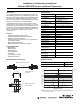
LED Illumination Pattern Connector Pinout
Frequently Asked Questions
Reference the product manuals for more specific installation
and configuration information. Manuals are available at
www.ab.com/rfid
.
Approximate Dimensions [mm (in.)]
Dimensions are not intended to be used for installation purposes.
LED Display Content
Module
Status
LED
Green light Power ON
No illumination No power
Read/
Write LED
Green light Normal operation
Solid green Communicating
Solid amber Sensing tag
Flashing red Communication error
Pin Signal
1 24V DC
2Data +
3GND
4Data -
Installation of Allen-Bradley products should
be in accordance with local and/or national
codes. Servicing energized industrial control
equipment can be hazardous if not in
accordance to recommended safety
procedures.
4
3
1
2
IMPORTANT
Read/Write
Status LED
M18x1
M12x1
16.6
(0.65)
35.8 (1.41)
12.2
(0.48)
63 (2.5)
73 (2.9)
7
(0.28)
16.6
(0.65)
dia
dia
Module
Status LED
Nut
Washer
Torque mounting nuts to 19.8N-m (14.6 ft-lb).
Nuts and washers included.
Tightening Torque
Mounting Brackets
Replacement Nuts and Washers
Description Cat. No.
Swivel/tilt style 60-2649
Right angle style 871A-BRN18
Description Cat. No.
Nut 871C-N3
Washer 871A-LWN18