
Installation Instructions Owner manual

Drwg. No. 10000181841 Ver 01
March 2012
Printed in USA
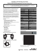
LED Illumination Pattern Connector Pinout
Frequently Asked Questions
Reference the product manuals for more specific installation
and configuration information. Manuals are available at
www.ab.com/rfid
.
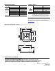
Approximate Dimensions – mm (in.)
Dimensions are not intended to be used for installation purposes.
LED Display Content
Module Status
LED
Green light Power ON
No illumination No power
Read/Write
LED
Green light Normal operation
Flashing green (short interval) Communicating
Flashing amber (short interval) Sensing tag
Flashing red (long interval) Communication error
Flashing green (long interval) No tag
Pin Signal
1 24V DC
2Data +
3GND
4Data -
IMPORTANT: Installation of Allen-Bradley products should be in
accordance with local and/or national codes. Servicing
energized industrial control equipment can be hazardous if
not in accordance to recommended safety procedures.
4
3
1
2
94
(3.7)
65
(2.56)
65
(2.56)
83
(3.27)
106.5
(4.19)
40
(1.57)
0.2
(0.01)