Rockwell Automation ControlLogix AutoMax DCSNet and AutoMax Remote I/O Communication Interface Module (Cat. No.
Page 2 AutoMax DCSNet /RE RIO Module Important User Information Solid state equipment has operational characteristics differing from those of electromechanical equipment. “Safety Guidelines for the Application, Installation and Maintenance of Solid State Controls” (Publication SGI1.1) describes some important differences between solid state equipment and hard–wired electromechanical devices.
56AMXN/B AUTOMAX DCSNET/RE RIO MODULE 6 Overview 6 Differences from the 56AMXN/A 7 Hardware Features 9 Other Requirements 9 INSTALLATION 10 Prevent Electrostatic Discharge 10 Set the Switches 10 Prepare the Chassis for Module Installation Determine Module Slot Location Insert the Module in the Chassis 11 11 11 Cabling and Termination 12 Software Installation 13 QUICK START 14 DCS Master and Slave 14 Remote I/O Master 14 CONNECTIONS AND TAGS 16 Connections Listen Only Comm Forma
Page 4 AutoMax DCSNet /RE RIO Module Remote I/O Master Using the Configuration Signature Importing Tags Configuring Input-Only Connections 26 28 29 29 USING THE DCS CONFIGURATION PROGRAM 32 DCS Bridging 32 USING THE 56AMXN AS A REMOTE I/O MASTER 35 The Configuration Program 35 Procedure 35 AutoConfiguring from the Network 36 Uploading a Configuration from the 56AMXN 36 The Network Tree 36 Remote I/O Tags 38 The Configuration Signature 38 USING THE MSG INSTRUCTION TO ACCESS 56AMXN DATA
LEDs NET LED – DCS/RIO Network Status CLX LED – ControlBus Status OK LED – Module Health All LEDs Red 61 61 61 62 62 4-Character Display 62 Using 56AmxnMon for Troubleshooting 63 Reading Diagnostic Counters into the ControlLogix Program 64 Using RSLogix 5000 to Diagnose Problems General Tab Connection Tab Module Info Tab Backplane Tab 64 64 64 65 66 UPDATING THE FIRMWARE 67 DCS NETWORK UPDATE TIME 68 SPECIFICATIONS 69 SUPPORT 70
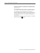
56AMXN/B AutoMax DCSNet/RE RIO Module Overview This document is a user guide for the 56AMXN/B module, which allows a Rockwell Automation ControlLogix backplane to communicate with an AutoMax DCS network or an AutoMax Remote I/O network. The module can act as a DCS master, a DCS slave or a remote I/O master. For DCS master or slave operation, the 56AMXN/B uses a specific RSLogix 5000 56AMXN module profile; for Remote I/O Master operation, it uses the 1756-MODULE generic module profile.
AutoMax DCSNet/RE RIO Module Page 7 • Supports up to 248 words of scheduled output data and 250 words of scheduled input data • Maintains diagnostic counters As either a DCS master or slave, the module supports bridging, which means that it can obtain its transmit data for any drop from another 56AMXN module in the same chassis. You can use a DDE or OPC server, such as RSLinx, capable of accessing the ControlLogix backplane, to access the DCS data directly on the 56AMXN.
Page 8 AutoMax DCSNet /RE RIO Module In remote I/O operation, if the ControlLogix was in program mode, the 56AMXN/A set outputs to 0. If there was a loss of connection, outputs held their last state The 56AMXN/B firmware sets the outputs to 0 in program mode or on loss of connection in DCS Master and Slave and Remote I/O operation. The 56AMXN/B is backward compatible with the 56AMXN/A. Applications written for the 56AMXN/A do not require modification to run on the 56AMXN/B.
AutoMax DCSNet/RE RIO Module Page 9 Hardware Features The following diagram shows the features of the module.
Page 10 AutoMax DCSNet /RE RIO Module Installation Prevent Electrostatic Discharge The module is sensitive to electrostatic discharge. ATTENTION: Electrostatic discharge can damage integrated circuits or semiconductors if you touch backplane connector pins.
AutoMax DCSNet/RE RIO Module Page 11 error message on the 4-character display but does not enter Thumbwheel test mode. Prepare the Chassis for Module Installation Before you install the module, you must install and connect a ControlLogix chassis and power supply. To install these products, refer to the installation instructions you received with them. Determine Module Slot Location This example shows chassis slot numbering in a 4-slot chassis.
Page 12 AutoMax DCSNet /RE RIO Module Figure 2 Inserting the 56AMXN Cabling and Termination Use drop cable (612574-36R) and passive tap (M/N 57C380) to connect the module to the coaxial network cable. This cable turns down and has a ferrite to reduce EMI. This cable must be used in CE applications. You can also use drop cable 612403-036R which points up. The drop cable is a 3-foot long multiconductor cable with 9-pin D-shell connectors at each end.
AutoMax DCSNet/RE RIO Module Page 13 The network coaxial cable must be terminated with 75 ohm terminating loads attached to the taps at the physical ends of the network. There should be two and only two terminators on the network. For DCS, the network cable can be RG-59/U or RG-11/U. For remote I/O, the cable must be RG-59/U. Software Installation The 56AMXN is supplied with a CD that includes the configuration and monitoring programs for the 56AMXN.
Page 14 AutoMax DCSNet /RE RIO Module Quick Start The following sections provide a brief summary of the steps necessary to get the module running in each mode. DCS Master and Slave 1. Set the switches on the 56AMXN module and install the module in the ControlLogix rack. 2. Run RSLogix 5000. If there a choice of RSLogix versions, select version 12 or above. 3. Create a new file or open an existing file. If necessary, select the appropriate processor properties. 4.
AutoMax DCSNet/RE RIO Module Page 15 8. You can now write your ladder logic using the tags you imported, download the program, etc.
Page 16 AutoMax DCSNet /RE RIO Module Connections and Tags Connections When you add a 56AMXN to the I/O Configuration of a ControlLogix, a broadcast data connection and from one to eight data connections are created. The number of connections is determined by the Comm Format you select when you add the 56AMXN module. The broadcast connection always updates every 3 ms. The data connections update at a rate from 3 ms to 750 ms, based on the RPI selected on the Connection tab for the module entry.
AutoMax DCSNet/RE RIO Module Page 17 will see the same input data as the ControlLogix with the owning Comm Format, but it will have no configuration or output data tags. More than one processor can use a Listen Only Comm Format to obtain input data from the same 56AMXN, as long as an owner exists.
Page 18 AutoMax DCSNet /RE RIO Module Figure 3 Configuration Tag The Configuration tag consists of an InputDropMap and an OutputDropMap section. The number of entries in each section depends on the Comm Format (Master 7 Drops, Master – 14 Drops, etc.) Each entry contains 7 blocks. You write values to each block to tell the 56AMXN which drop’s data will appear in the corresponding section of the input and output drop data tags.
AutoMax DCSNet/RE RIO Module Page 19 InputDropMap Value Description 1 to 55 Drop data from drops, registers 0 to 31 56 Unused Any other Invalid OutputDropMap Value Description 1 to 55 Drop data to remote drops, registers 32 to 63 56 Unused Any other Invalid DCS Slave InputDropMap Value Description 0 56AMXN Status/diagnostic registers 1 to 55 Drop data, registers 32 to 63, from master -1 to –55 Drop data, slave to master, registers 0 to 31, from monitored drops 56 Unused Any other I
Page 20 AutoMax DCSNet /RE RIO Module For example, you can inhibit the connection, then remove the inhibit to break and remake all connections. I and O Tags The I and O tags are associated with the broadcast connection. The contents vary depending on whether the 56AMXN is a DCS master or slave. DCS Master The I tag contains a single DINT, Fault, which is 1 if no slaves are connected and is 0 otherwise. In addition, the fault is -1 (16#FFFF FFFF) if the connection is not active.
AutoMax DCSNet/RE RIO Module Page 21 Bits Description 0-6 Input mapped drop offline 8-14 Output mapped drop offline 16-22 Monitored mapped drop offline (slave only) Table 3 Input Fault Bits Global Status Registers The 56AMXN diagnostic/status registers can be mapped into one of the input tags by writing a 0 to the entry in the Configuration tag. They may provide useful information on the operation of the network. Registers 4-7 contain the drop status table.
Page 22 AutoMax DCSNet /RE RIO Module Register 16 contains CRC errors. This counter increments when the module receives a packet with a bad CRC. Register 17 contains overrun errors. This counter increments when the module receives a packet that is longer than 272 bytes. Register 18 contains abort errors. This counter increments when the module starts to receive a packet but the packet is never completed. Register 19 contains a running count of messages transmitted.
AutoMax DCSNet/RE RIO Module Page 23 Configuring the Module in RSLogix 5000 You configure the module in RSLogix 5000 to set the module type, how much scheduled data to transfer and how often to transfer it, and what data to transfer. The details of the configuration depend on whether the module is being used as a DCS master or slave, or as a remote I/O master. DCS Master or Slave Adding the Module To configure the module in RSLogix 5000 for use as a DCS Master or Slave, you must be offline. 1.
Page 24 AutoMax DCSNet /RE RIO Module 4. Assign the module a Name and optionally a Description. 5. Set the Slot to match the slot number of the module in the chassis. 6. Select a Comm Format from the list. Select a master or slave connection. Choose a Comm Format that is large enough for the anticipated number of drops on the network. Too small means you can’t map all the data; too large and you add extra traffic to the backplane.
AutoMax DCSNet/RE RIO Module Page 25 The network update time is approximately 3 ms per drop (see page 68). Keep this in mind when selecting an RPI. There is no point in selecting an RPI that is much faster than the network update time since the network data will not update as fast as the RPI. In addition, it just adds to the ControlLogix backplane traffic. 9. Click Finish >> to complete the module configuration. 10.
Page 26 AutoMax DCSNet /RE RIO Module Figure 6 Module Properties 1 7. Set the module RPI. This is how often the module’s scheduled data is updated in the processor. The value can range from 3.0 to 750 ms. The default is 3 ms. The listen only RPI should match the RPI for the owning ControlLogix. 8. Click Finish >> to complete the module configuration. 9. Save the program and download it to the ControlLogix processor. Remote I/O Master To configure the module in RSLogix 5000, you must be offline. 1.
AutoMax DCSNet/RE RIO Module Page 27 Figure 7 Module Properties Dialog 1 4. Assign the module a Name and optionally a Description. 5. Set the Comm Format to Data – INT – with Status. 6. Set the Slot to match the slot number of the module in the chassis. 7. The Input Assembly Instance should be 1. The size should be large enough to allow all the data to be passed (or larger). The maximum size is 250 words. The minimum size is determined by the largest offset assigned to input data. 8.
Page 28 AutoMax DCSNet /RE RIO Module Figure 8 Module Properties Dialog 2 Connection Parameters 13. Set the module RPI. This is how often the module’s scheduled data is updated in the processor. The value can range from 0.2 to 750 ms. The default is 5 ms. 14. Click Finish >> to complete the module configuration. Using the Configuration Signature The Remote I/O configuration program computes a configuration signature that is a CRC based on the current I/O configuration.
AutoMax DCSNet/RE RIO Module Page 29 until the connection is closed and reopened, for example, by cycling power, or by removing and reinserting the module. You can disable Configuration Signature checking by entering FF FF FF FF in the configuration data for the module in RSLogix 5000. Refer to page 38 for information on obtaining the value to use for the configuration signature. Importing Tags To import the tags exported from the Remote I/O configuration program: 1. Select Tools/Import Tags… 2.
Page 30 AutoMax DCSNet /RE RIO Module Figure 9 Module Properties 1 3. Assign the module a Name and optionally a Description. 4. Set the Comm Format to Input Data – INT – With Status 5. Set the Slot to match the slot number of the 56AMXN module in the chassis. 6. The Input Assembly Instance should be 1. The size should be large enough to allow all the data to be passed (or larger). The maximum size is 250 words. The minimum size is determined by the largest offset assigned to input data. 7.
AutoMax DCSNet/RE RIO Module Page 31 Figure 10 Module Properties 2 12. Set the module RPI. This is how often the module’s scheduled data is updated in the processor. The value can range from 0.2 to 750 ms. The default is 5 ms. 13. Click Finish >> to complete the module configuration. All connections to the module must have the same lengths and RPIs.
Page 32 AutoMax DCSNet /RE RIO Module Using the DCS Configuration Program The DCS Configuration program was used for the 56AMXN/A to configure the drop data mapped to scheduled data. You do not need to use the DCS Configuration program to configure drops scanned by the 56AMXN/B. Drop configuration is done by writing to the module’s Configuration tag in RSLogix 5000. The only purpose for using the configuration program is to configure DCS bridging.
AutoMax DCSNet/RE RIO Module Page 33 updates the bridged drop. If the data was just about to be updated on the source, the worst case data update time is the scan time on the source module’s network + 3 ms. To configure a drop as a bridged drop: 1. Start the configuration program. From the start menu select Programs/56AMXN/56AmxnDcsCfg 2. Right click on the root of the network tree in the left pane (by default it says 56AMXN – Drop 00) and select Edit 56AMXN. Figure 12 56AMXN Drop Number 3.
Page 34 AutoMax DCSNet /RE RIO Module Figure 14 Bridging 7. For the Type, select DCS_REG to obtain the data from the source module's DCS registers NOTE: the 56AMXN/B does NOT support CLX bridging. 8. Select: • the CLX slot the source module resides in, 0-16 • the drop number of the data to be collected, 0-55 • the starting register, 00 or 32 9. Click OK. 10. To download the configuration to the 56AMXN, right click on the root of the network tree in the left pane and select Configure 56AMXN.
AutoMax DCSNet/RE RIO Module Page 35 Using the 56AMXN as a Remote I/O Master As a Remote I/O master, the module: • Scans up to 7 drops • Supports up to 248 words of scheduled output data and 250 words of scheduled input data • Maintains diagnostic counters You configure the module using the utility provided. It reads the online network and stores the network configuration in flash memory on the 56AMXN.
Page 36 AutoMax DCSNet /RE RIO Module 5. Run RSLogix 5000 and configure the module. 6. Import the tags you exported from 56AmxnRioCfg into RSLogix 5000. 7. Enter the Configuration Signature in the configuration data for the module in RSLogix 5000. You can now write your ladder logic using the tags you imported, download the program, etc.
AutoMax DCSNet/RE RIO Module Page 37 Figure 15 56AmxnRioCfg The tree is divided into three main areas: • The Configuration Signature • ControlLogix Inputs • ControlLogix Outputs You can expand each area to show its contents. The interpretation of the number or numbers shown after the tree elements depends on what type of element it is. For Inputs and Outputs, the number indicates the number of registers of each type.
Page 38 AutoMax DCSNet /RE RIO Module Remote I/O Tags 56AmxnRioCfg creates a tag file that consists of aliases to data locations. The format of the alias name indicates the location of the data on the remote I/O network.
AutoMax DCSNet/RE RIO Module Page 39 Using the MSG Instruction to Access 56AMXN Data You can use ControlLogix MSG instructions to access data in various objects on the 56AMXN module. For example, you can access any data on the DCS network using MSG instructions to the custom DCS data object. To use a MSG instruction, you create a tag of type MESSAGE to act as a control for the MSG instruction and source and destination tags for the MSG data. You must also enter the path to the 56AMXN module.
Page 40 AutoMax DCSNet /RE RIO Module of service, instance, and attribute makes it possible to read or write the data on any DCS drop. There are instructions that read and write the data on single drops and instructions that read and write data on multiple drops. Note that these instructions allow you to write to areas of the network memory map that AutoMax would not allow.
AutoMax DCSNet/RE RIO Module Page 41 Service (hex) Name Function 04h Set Attribute List Set the data for up to 7 drops 0eh Get Attribute Single Get the data for a single drop 10h Set Attribute Single Set the data for a single drop 32h DCS Register Raw Write Write a block of data to the DCS registers on the 56AMXN 33h DCS Register Raw Read Read a block of data from the DCS registers on the 56AMXN 36h Write Multiple Drops Set the data for up to 7 drops 37h Read Multiple Drops Get the d
Page 42 AutoMax DCSNet /RE RIO Module Length (bytes) Destination Enter the destination tag name, must be large enough to hold the data, make it an integer array of size at least 32 integers Table 10 DCS Data Object Instance Level Get Attribute Single Parameters This command can be used to read the DCS data for any drop, including drop 0. You enter the drop number as the attribute, and use the instance to select whether you want to read registers 0-31 or 32-63.
AutoMax DCSNet/RE RIO Module Page 43 you would write to registers 0-31 as a DCS slave and to registers 32-63 as a DCS master. The length for attribute 0 is a special case. For instance 1, the size must be 12 (6 words). The command writes to registers 14-19, the diagnostic counters. For example, you could use this command to clear diagnostic counters. For instance 2, the size must be 16 (8 words). The command writes to the broadcast registers (32-39). Normally you would do this only as a DCS master.
Page 44 AutoMax DCSNet /RE RIO Module In the source tag, the data consists of: # of attributes First Attribute # Second attribute # And so on. The reply consists of: # of attributes First Attr # Status for first attribute Data[32] for first attribute Second Attr # Status for second attribute Data[32] for second attribute and so on. The attribute status reflects the status of the drop in the active drop list.
AutoMax DCSNet/RE RIO Module Page 45 Length (bytes) Destination Destination tag name Table 13 Get Attribute List Example In the source tag, an array of at least 4 integers, we would enter: 3 (number of attributes) 1 (first attribute) 4 (second attribute) 7 (third attribute) The reply written to the destination tag would consist of: 3 (number of attributes) 1 (status of first attribute, drop 1) 32 integers of data for drop 1 1 (status of second attribute, drop 4) 32 integers of data for drop 4 1 (status of
Page 46 AutoMax DCSNet /RE RIO Module Instance 1 for registers 0-31 2 for registers 32-63 Attribute (hex) leave blank Source Element enter source tag name Source 2 + [number of attributes] * 66, see table below Length (bytes) Destination enter destination tag name, it doesn’t matter but it must be entered.
AutoMax DCSNet/RE RIO Module Page 47 For instance 2, the size must be 16 (8 words). The command writes to the broadcast registers (32-39). Normally you would do this only as a DCS master. The maximum message size limits the number of attributes you can write in a single message to 7. DCS Raw Write, Service Code 32h The DCS raw write command can be used to write a block of data to the DCS data area on the module. You tell it the starting offset and the data length and it writes the data.
Page 48 AutoMax DCSNet /RE RIO Module DCS Raw Read, Service Code 33h The DCS raw read command can be used to read a block of data from the DCS data area on the module. You tell it the starting offset and the data length and it reads the data.
AutoMax DCSNet/RE RIO Module Page 49 Message Type CIP generic Service Type Custom Service Code 37h Class (hex) C4h Instance 1 for registers 0-31 (master or slave) 2 for registers 32-63 (master or slave) Attribute (hex) leave blank Source Element enter source tag name Source 2 + Number of drops * 2 Length (bytes) Destination enter destination tag name Table 18 Read Multiple Drops Parameters Message format in the source tag # of drop First drop # Second drop # … Last drop # The Reply data consi
Page 50 AutoMax DCSNet /RE RIO Module 4 128 5 160 6 192 7 224 If you create an array organized as Data[number of drops][32] to hold the returned data, it makes it very easy to locate the data for each drop and register. Write Multiple Drops, Service Code 36h This command is similar in purpose to Set Attribute List, except that the layout of the data is more intuitive and makes it easier to locate the data for a specific drop and register.
AutoMax DCSNet/RE RIO Module Page 51 … Data for the first drop in the list, 32 words # of drops First Drop # Second drop # … Last drop # with up to 7 attributes and data arrays Note that Write Multiple Drops does not support drop 0 Drops Source Length (bytes) 1 68 2 134 3 200 4 266 5 332 6 398 7 464 Nothing is written to the destination tag.
Page 52 AutoMax DCSNet /RE RIO Module Create a MSG instruction using the service code, class, instance and attribute described above. For the source, enter the tag name Data. For the Source Length (bytes), enter 200 (from the table, we’re writing 3 drops). Enter a tagname for the destination. Finally, on the Connection tab, type or browse the path to the 56AMXN module.
AutoMax DCSNet/RE RIO Module Page 53 Using DDE/OPC to Access DCS Data on the Module You can use a DDE or OPC server such as RSLinx, or any other HMI capable of accessing the ControlLogix backplane, to access the DCS data directly on the 56AMXN. The module “emulates” PLC-5 integer files 100-155. Each file corresponds to a DCS drop. For example, if you create tags to access N102, N102:0 to N102:63 represent Drop 2’s DCS registers.
Page 54 AutoMax DCSNet /RE RIO Module Using the Monitor Program 56AmxnMon is a program that lets you monitor the operation of the 56AMXN ControlLogix AutoMax module and perform maintenance operations.
AutoMax DCSNet/RE RIO Module Page 55 Monitoring DCS Registers Select Monitor/DcsRegs to monitor the AutoMax DCS registers on any drop. Figure 17 DCS Register Display Use the Drop listbox to select the drop number to display. For drops 1-55, registers 0-31 contain the data from the slave to the master. Registers 32-63 contain the data from the master to the slave. WARNING! If you change values in the DCS registers, the values on the module will change.
Page 56 AutoMax DCSNet /RE RIO Module By default the register contents are shown in decimal. Uncheck Decimal to display the register contents in hexadecimal. DCS registers apply only to DCS master and slave operation. If you attempt to monitor DCS registers when the module is configured for remote I/O operation, 56AmxnMon returns an error. DCS data can also be displayed in RSLogix 5000 using Monitor Tags to display the appropriate tags.
AutoMax DCSNet/RE RIO Module Page 57 By default the contents of the registers are shown in decimal. You can display the contents in hexadecimal by unchecking the Decimal checkbox. WARNING! If you change values in the CLX registers, the values on the module will change. Consider the consequences of changing the data. You can use 56AmxnMon to change values in CLX registers. Before you can do this, you must check Allow Edits. You will be asked to confirm this.
Page 58 AutoMax DCSNet /RE RIO Module • Msg Recv, counts packets successfully received by the module • Recv Timeouts, applies only when the module is the DCS master. They occur when a reply packet isn’t received within the timeout period.
AutoMax DCSNet/RE RIO Module Page 59 Active Drop List The Active Drop List shows which DCS drops are active on the network. For Remote I/O operation, only drops 1-7 are valid. The Debug Log The firmware on the module sends trace messages that indicate its internal state of operation and show any minor errors it encounters. These messages are often useful for determining why connections have errors or for technical support. To display these messages, select View/Monitor Debug Log.
Page 60 AutoMax DCSNet /RE RIO Module Fatal Errors Fatal errors occur when the firmware on the module encounters an unexpected condition. The module stops scanning, turns all three LEDs red, displays the fatal error number on the 4-character display, and stores a fatal error log that indicates the cause of the fatal error. To clear the fatal error and capture the fatal error log: 1. Cycle power on the module. The 4-character display should show “FatalErrorCapture required”. 2.
AutoMax DCSNet/RE RIO Module Page 61 Troubleshooting LEDs The 56AMXN module has three LEDs that indicate the state of the network connection, the connection to the ControlLogix processor, and the overall module health. These LEDs can be used in conjunction with the 4-character scrolling display and the monitor program 56AmxnMon to determine the cause of the problem. NET LED – DCS/RIO Network Status The NET LED indicates the status of the network connection. It is green if the network status is good.
Page 62 AutoMax DCSNet /RE RIO Module OK LED – Module Health A bicolor OK LED indicates module health. A red LED indicates that module startup diagnostics have failed or a major module fault such as watchdog timeout or jabber inhibit has occurred. Green indicates that the card has passed all power-up diagnostics and is functioning normally. This LED is red during powerup.
AutoMax DCSNet/RE RIO Module Page 63 Message Description Depth=xx the drop number and drop depth shown. Displayed during normal operation. Drop xx Timeout DCS drop xx has timed out. Mon Drop xx Timeout Monitored DCS drop xx has timed out. Firmware Update... The firmware on the module is being updated. Error: Heard Another RIO Master The module is configured as a Remote I/O master and has heard another Remote I/O master active on the network.
Page 64 AutoMax DCSNet /RE RIO Module You can use 56AmxnMon to display the active drop list and the diagnostic counters for both DCS and RIO network communication, and diagnostic counters for the backplane communication with the ControlLogix processor. To troubleshoot problems with DCS data, you can use 56AmxnMon to view the raw DCS data coming in to the module from the network for being sent to the network.
AutoMax DCSNet/RE RIO Module Page 65 56AMXN refuses a connection from the processor, an error will be displayed Value Description and possible cause 16#000C Service request error: Invalid mode or state for service request. The 56AMXN is unable to process the request in the current mode 16#0009 Module configuration rejected. Parameter error.
Page 66 AutoMax DCSNet /RE RIO Module • Minor fault • Internal state • Configured • Owned • Module Identity The Refresh Button updates the information on the screen. Backplane Tab The ControlBus Status shows any backplane faults, or OK if there are no faults. ControlBus Parameters The Multicast CRC error threshold is fixed at 8. The Transmit Retry Limit defaults to 45 but can be edited. Chassis The Chassis area contains information that relates to the chassis, not the module.
AutoMax DCSNet/RE RIO Module Page 67 Updating the Firmware The card supports firmware and FPGA upgrade across the ControlLogix backplane using the Rockwell ControlFlash utility. Install the ControlFlash software from the 56AMXN distribution CD and run it as you would to update any other ControlLogix module. Refer to the ControlFlash documentation and help for detailed information on how to use ControlFlash. A 56AMXN/A can be upgraded to 56AMXN/B functionality by simply upgrading the firmware.
Page 68 AutoMax DCSNet /RE RIO Module DCS Network Update Time From the manual for the 57C404B (publication J2-3001-3), the DCS network update time is given by: Update time = (DropTime * N) + NewDropTestTime + MessageTime where DropTime = the amount of time for a master to send a message and the slave to respond = 2.99 ms N = Number of slave drops (physical and virtual) NewDropTestTime = amount of time for the master to poll an inactive drop and wait for its response = 2.
AutoMax DCSNet/RE RIO Module Page 69 Specifications The 56AMXN/B is a standard ControlLogix module with the following specifications: Parameter Specification Module Location ControlLogix chassis Function ControlLogix AutoMax DCS and Remote I/O module Description Processor: 100MHz IDT MIPS FLASH memory: 1Mbyte (512Kx16) Local RAM: 1Mbyte (256Kx32) 50Mhz synchronous SRAM Shared RAM: 512Kbyte (128Kx32) 20ns asynchronous SRAM Maximum Backplane Current Load 650mA @ +5.
Page 70 AutoMax DCSNet /RE RIO Module Support Local Drive Solutions Contact Directory New England Ph. 508.357.8431 Fax 508.485.5059 Boston MA Southeast Ph. 770.277.0277 Fax 770.682.6491 Atlanta GA Gulf Coast Ph. 281.233.0300 Fax 281.233.0101 Houston TX West Coast Ph. 626.969.7647 Fax 626.334.8320 Los Angeles CA Eastern Ph. 732.225.1360 ext. 110 Fax 732.225.7833 Edison NJ Carolinas Ph. 704.525.1455 Fax 704.525.9025 Charlotte NC Midwest Ph. 630.860.1090 Fax 630.787.0309 Chicago IL St. Ph. Fax St.
www.rockwellautomation.com Corporate Headquarters Rockwell Automation, 777 East Wisconsin Avenue, Suite 1400, Milwaukee, WI, 53202-5302 USA, Tel: (1) 414.212.5200, Fax: (1) 414.212.5201 Headquarters for Allen-Bradley Products, Rockwell Software Products and Global Manufacturing Solutions Americas: Rockwell Automation, 1201 South Second Street, Milwaukee, WI 53204-2496 USA, Tel: (1) 414.382.2000, Fax: (1) 414.382.