
Owner's manual

Chapter 3
Using Local I/O
3–12
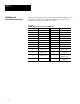
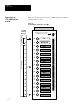
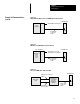
Tables 3.A through 3.H show the connector pin assignments with the various
combinations of Series A and Series B CVIM modules connected to I/O
Interface Boxes (Catalog Nos. 2801–N21, –N27) .
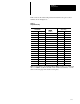
Table 3.A
CVIM Module I/0 Connector: Series A CVIM Module
Pin Number Function Pin Number Function
1 Trigger Input Line #1 14 Output Line #12
2 Trigger Input Line #2 15 Output Line #13
3 Output Line #1 16 Output Line #14
4 Output Line #2 17 Reserved
5 Output Line #3 18 Reserved
6 Output Line #4 19 Ground (Power)
7 Output Line #5 20 Ground (Power)
8 Output Line #6 21 Ground (Chassis)
9 Output Line #7 22 Ground (Signal)
10 Output Line #8 23
TXD (Transmit
Data: RS–232 A)
11 Output Line #9 24
RTS (Request to Send:
RS–232 A)
12 Output Line #10 25
RXD (Receive
Data: RS–232 A)
13 Output Line #11 26
CTS (Clear to Send:
RS–232 A)
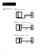
CVIM Module I/O
Interface Box Connections