
Owner's manual

Chapter 3
Using Local I/O
3–10
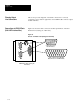
This section provides diagrams of electrical connections for correctly
connecting your production equipment to the CVIM module’s discrete output
and RS–232 lines.
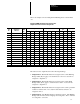
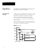
Figure 3.6 shows the cable connectors and their pin numbers on the I/O
Interface Box (Catalog No. 2801–N27).
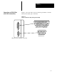
Figure 3.6
Pinouts– I/O Interface Box (Catalog No. 2801–N27)
P
O
R
T
A
1
234567
10
89
18
19
20212223242526
11121314151617
6
1
2345
789
Cable connectors to
RS–232 devices.
Cable connector from Module
I/O connector on CVIM Module.
I/O Interface Box (Catalog No.
2801–N27)
P
O
R
T
B
C
V
I
M
Planning Output
Line Connections
Connections to RS–232 Ports
(2801–N27 Interface Box)