
Owner's manual

Chapter 3
Using Local I/O
3–7
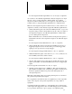
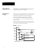
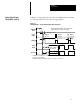
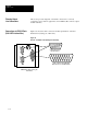
In Figure 3.3, trigger pulse #2 occurs before the CVIM module has finished
processing the inspection cycle started by trigger pulse #1.
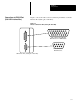
Figure 3.3
Timing Diagram — Trigger #2 During Data Valid, Pulsed I/O
You can select
a pulse width of
1 to 2000 ms
Min. Strobe ≈ 1ms
Min. trigger ≈ 2ms*
MODULE
BUSY
** ***
***
Trigger
pulse #1
Trigger
pulse #2
Trigger
(Input)
STROBE
DATA
VALID
RESULTS
Max. lag ≈ 1ms
** Minimum acquisition time: 17ms for 256x256 and 512x256 Res; 34 ms for 512x512 res.
*** Analysis time (variable).
DATA VALID will always pulse high when
inspection processing is complete
Trigger
pulse #3
For Trigger #1
***
****RESULTS will pulse high if an analysis tool range is exceeded.
For Trigger #2 For Trigger #3
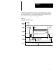
Using Output Signal
Timing Data (cont’d)