
Owner's manual

Chapter 3
Using Local I/O
3–3
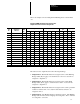
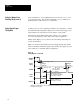
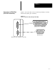
Here is an example of how an Output Line Planning Sheet could be filled
out:
Example CVIM Module Output Line Planning Sheet
Output Line Functions and Tool Assignments
Line Output Line
Tool
Set
Gage Window
Reference
Tool
Light Probe
No. Function
Set
No.
No. Rng. No. Rng. No. Rng. No. Rng. Line Win. Cam. Rng.
1 Results 1 1 W 2 W 1 W 2 W
″ ″ ″ 3 W 4 W
2 Results 1 1 F 2 F 1 F 2 F
″ ″ ″ 3 F 4 F
3 Results 1 1 1
4 Results 1 A W
5 Results 1 A F
6 Results 2 1 W 1 F
″ ″ ″ 2 W 2 F
7 Strobe 1
8 Trig. NAK 1
9 Master Fault 1
10 Data Valid 1
11 Module Busy NA
12 Not Used
13 Not Used
14 Not Used
The entries for the output lines have the following meanings:
• Output Line 1: The Results function is assigned to line 1. The Warning
Range results (W) for gages 1–4 and windows 1 and 2 of toolset #1 are
assigned to output line 1.
• Output Line 2: The Results function is assigned to line 2. The Fault
Range results (F) for gages 1–4 and windows 1 and 2 of toolset #1 are
assigned to output line 2.
• Output Line 3: The Results function is assigned to line 3. The “pass/fail”
results for reference line 1 of toolset #1 and reference window 1 are
assigned to line 3.
• Output Line 4: The Results function is assigned to line 4. The Warning
Range result from the camera A light probe is assigned to line 4. Camera
A is assigned to toolset #1.