
Owner's manual

Appendix D
Configuration Data
D–11
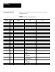
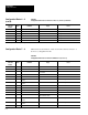
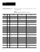
Table D.7
Configuration Blocks #37–39 – Reference Lines 1–3 (Toolset 2)
Remote I/O
& RS–232
Word #
Bit # Definition Usage Notes
23 0–15 Reserved
24 0–15 X/Y–Line Head X Position From upper left corner.
25 0–15 X/Y–Line Head Y Position From upper left corner.
26 0–15 X/Y–Line Tail X Position From upper left corner.
27 0–15 X/Y–Line Tail Y Position From upper left corner.
28–29 0–15 Reserved
* Refer to Chapter 6 for Pyramid Integrator long word descriptions.
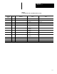
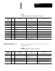
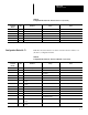
Table D.8 shows the function of each word in the reference window 1–3
(Toolset 2) configuration blocks.
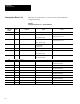
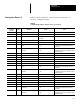
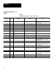
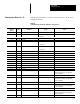
Table D.8
Configuration Blocks #69–71 – Reference Windows 1–3 (Toolset 2)
Remote I/O
& RS–232
Word #*
Bit # Definition Usage Notes
0 0–15 Block Transfer Signature
1 0–7 Reserved
1 8 Enable 0 = Disabled18Enable 0 = Disabled
1 = Enabled
1 9–15 Reserved
2–7 0– 15 Reserved
8 0– 15 Feature 1 Search Window X
Location
Relative to the upper left corner.
9 0– 15 Feature 1 Search Window Y
Location
Relative to the upper left corner.
10 0– 15 Feature 1 Search Window Width
11 0– 15 Feature 1 Search Window Height
12–15 0–15 Reserved
16 0–7 Reserved
16 8–15 Feature 1 Score 0 = Minimum Value
255 = Maximum Value
17 0–15 Feature 2 Search Window X
Location
Relative to the upper left corner.
18 0–15 Feature 2 Search Window Y
Location
Relative to the upper left corner.
* Refer to Chapter 6 for Pyramid Integrator long word descriptions.
Configuration Blocks 69–71