
Owner's manual

Appendix D
Configuration Data
D–8
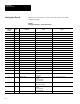
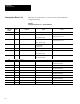
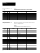
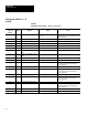
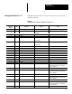
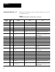
Table D.5
Configuration Blocks #10–41 – Gages 1–32 (Toolset 1)
Remote I/O
& RS–232
Word #*
Bit # Definition Usage Notes
4 8–15 High Threshold/Gradient Threshold 0 – 63
0 – 197
If binary operation, value is used as the
threshold high. If gray scale operation, value is
gradient threshold.
5 0–15 Reserved
6 0–15 Gage Head X Position
7 0–15 Gage Head Y Position
8 0–15 Gage Tail X Position
9 0–15 Gage Tail Y Position
10 0–15 Gage X Center Position (Circular
Gage)
11 0–15 Gage Y Center Position (Circular
Gage)
12 0–15 Radius of Circular Gage
13–16 0–15 Reserved
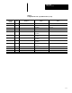
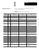
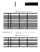
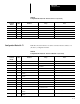
17 0–15 Fail Range High (Integer) Words 17 and 18 represent a 16(bit) . 16(bit)
fixed point decimal value or 32 bit integer.
Refer to Appendix A.
18 0–15 Fail Range High (Fraction)
19 0–15 Fail Range Low (Integer) Words 19 and 20 represent a 16(bit) . 16(bit)
fixed point decimal value or 32 bit integer.
Refer to Appendix A.
20 0–15 Fail Range Low (Fraction)
21 0–15 Warning Range High (Integer) Words 21 and 22 represent a 16(bit) . 16(bit)
fixed point decimal value or 32 bit integer.
Refer to Appendix A.
22 0–15 Warning Range High (Fraction)
23 0–15 Warning Range Low (Integer) Words 23 and 24 represent a 16(bit) . 16(bit)
fixed point decimal value or 32 bit integer.
Refer to Appendix A.
24 0–15 Warning Range Low (Fraction)
25–27 0–15 Reserved
* Refer to Chapter 6 for Pyramid Integrator long word descriptions.
Configuration Blocks 10 – 41
(cont’d)