
Owner's manual

Appendix D
Configuration Data
D–4
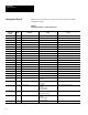
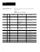
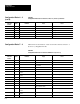
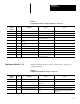
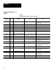
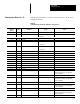
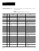
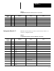
Tables D.2 shows the function of each word in the camera definition
configuration blocks.
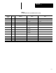
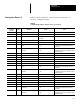
Table D.2
Configuration Block #2 & 3 – Camera Definition
Remote I/O
& RS–232
Word #*
Bit # Definition Usage Notes
0 0–15 Block Transfer Signature
1 0–7 Camera Low Reference 0 = Minimum Value
. . .
100 = Maximum Value
These values do not correspond with the
display on the help screen.
1 8–15 Camera High Reference 105 = Minimum Value
. . .
255 = Maximum Value
These values do not correspond with the
display on the help screen.
2
0–7 Light Probe Status 0 = Disabled
1 = Same Field
2 = Next Field
2 8–15 Reserved
3
0–15 Light Probe X Location 16 = Minimum Value
. . .
504 = Maximum Value
4
0–15 Light Probe Y Location 8 = Minimum Value
. . .
232 = Maximum Value
5–9 0–15 Reserved
10 0–15 Fail Range High (Integer) Words 10 and 11 represent a 16 (bit) . 16 (bit)
fixed point decimal value.
11 0–15 Fail Range High (Fraction)
12 0–15 Fail Range Low (Integer) Words 12 and 13 represent a 16(bit) . 16(bit)
fixed point decimal value.
13 0–15 Fail Range Low (Fraction)
14 0–15 Warning Range High (Integer) Words 14 and 15 represent a 16 (bit). 16 (bit)
fixed point decimal value.
15 0–15 Warning Range High (Fraction)
16 0–15 Warning Range Low (Integer) Words 16 and 17 represent a 16 (bit) . 16 (bit)
fixed point decimal value.
17 0–15 Warning Range Low (Fraction)
18–60 0–15 Reserved
* Refer to Chapter 6 for Pyramid Integrator long word descriptions.
Configuration Blocks 2 & 3