
Owner's manual

D
Appendix
D–1
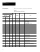
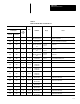
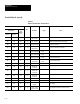
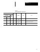
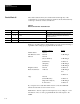
Configuration Data
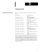
There are 135 configuration blocks. The following is an overview of the
blocks.
Block Number 1 System Environment. . . . . . . . . . . . . . . . . .
(45 words).
Block Numbers 2 and 3 Camera A and B Definition. . . . . . . . . . . .
(61 words each camera).
Block Numbers 4 through 6 Toolset 1 Reference Lines 1 through. . . . . . . . .
3 (30 words).
Block Numbers 7 through 9 Toolset 1 Reference Windows 1. . . . . . . . .
through 3 (36 words).
Block Number 10 through 41 Toolset 1 Gages 1 through 32 (28. . . . . . . .
words).
Block Numbers 42 through 65 Toolset 1 Windows 1 through 24 (37. . . . . . .
words).
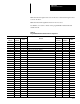
Block Numbers 66 through 68 Toolset 2 Reference Lines 1 through. . . . . . .
3 (30 words).
Block Numbers 69 through 71 Toolset 2 Reference Windows 1. . . . . . .
through 3 (36 words).
Block Numbers 72 through 103 Toolset 2 Gages 1 through 32 (28. . . . . .
words).
Block Numbers 104 through 127 Toolset 2 Windows 1 through 24 (37. . . . .
words).
Block Numbers 128 through 135 Polygon Blocks 1 through 8 (37. . . . .
words).
Note: When reading the configuration blocks, the PLC should set the block
length to 0. This will allow the CVIM module to set the block size based
upon the block number received. The CVIM module will then only send the
amount of data required for each block type. This helps reduce the overall
transfer time when writing. If the PLC sets the block length to 0 (64 words)
when writing to a CVIM module, the CVIM module will ignore excess data
at the end of each block. Alternatively, the PLC may set the exact length to
reduce the transfer time.
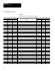
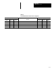
Configuration Block Overview