
Owner's manual


Chapter 2
Introduction
2–4
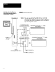
Depending upon the type of interface in use, you can access some or all of
the information listed below:
• Warning and Pass/Fail data.
• Numerical inspection results.
• Configuration data.
With each inspection that the CVIM module performs, individual bits are set.
There are 128 bits that can be read as inputs to a host device. These bits (part
of the inspection results) indicate:
• Master fault.
• Mastership.
• Configuration fault.
• Module Busy flag.
• Missed Trigger flag.
• Results Valid flag.
• Inspection Tool Pass/Fail/Warning flags.
There are 128 bits that can be set as outputs by a host device to control the
operation of the CVIM module. These bits control:
• Monitor display.
• Inspection trigger.
• Toolset selection.
• Enable/disable and force discrete I/O.
• Selection of operation after reject.
• Memory storage location. RAM, EEPROM, RAM Card, or external host
memory.
Note:
For more information on the 128 discrete input and 128 discrete output bits
refer to Appendix B.
What Types of Information
can be Communicated?
Discrete Bit Information