
Owner's manual
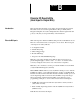

Appendix B
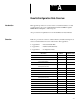
Discrete Bit Results
B–2
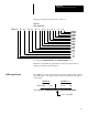
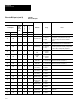
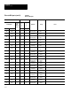
Table B.1
Discrete Bit Inputs
Word# Bit#
PI Backplane
RS–232
and
Remote
I/O
D
E
C
I
M
A
L
O
C
T
A
L
Definition Usage Notes
Toolset 1 Toolset 2 PI PLC
16 280 0 0 0 Not Used
16 280 0 1 1 Configuration Error
0 = No Error
1 = Error
Configuration error bit is set after any invalid
configuration or template block write to the
CVIM. This flag is also set after validation
errors.
16 280 0 2 2 Mastership Flag
0 = Not Master
1 = Master
The device which reads this bit as 1 is the host.
Not applicable for RS–232 communications.
16 280 0 3 3 Module Busy
0 = Not Busy
1 = Busy
Module Busy bit is set during the SETUP mode
and during a download (sending configurations
to the CVIM or reading/writing templates).
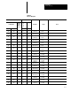
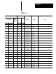
16 280 0 4 4
Trigger 1
NAK
0 = OK
1 = Trigger 1
Missed
16 280 0 5 5
Trigger 2
NAK
0 = OK
1 = Trigger 2
Missed
16 280 0 6 6
Toolset 1
Data Valid
0 = Not Valid
1 = Results Valid
Data Valid bit is reset when a user enters the
SETUP mode. Refer to Chapter 3.
16 280 0 7 7
Toolset 2
Data Valid
0 = Not Valid
1 = Results Valid
Data Valid bit is reset when a user enters the
SETUP mode. Refer to Chapter 3.
16 280 0 8 10
Reference
Line 1 Flag
0 = Pass
1 = Failed
16 280 0 9 11
Reference
Line 2 Flag
0 = Pass
1 = Failed
16 280 0 10 12
Reference
Line 3 Flag
0 = Pass
1 = Failed
16 280 0 11 13
Reference
Window 1 Flag
0 = Pass
1 = Failed
16 280 0 12 14
Reference
Window 2 Flag
0 = Pass
1 = Failed
16 280 0 13 15
Reference
Window 3 Flag
0 = Pass
1 = Failed
16 280 0 14 16 Light Probe Flag
0 = Pass
1 = Failed
16 280 0 15 17 Master Fault
0 = No Fault
1 = Fault
Master fault bit is set if any tool fails an
inspection.
17 281 1 0 0
Window 1
Warning Flag
0 = Pass
1 = Failed
Discrete Bit Inputs (cont’d)