
USER-PAK Option

Chapter 8
Defining Strings for Serial Ports and Viewports
8 – 17
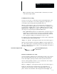
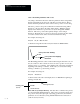
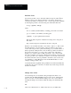
(10, 20)
(40, 60)
(0, 0)
Line drawn
Viewport border
Starting point
End point
The end point x- and y-coordinates in this example would be (40, 60). The
x-coordinate of the end point (40) is obtained by adding the dx value (30) to
the starting point x-coordinate value (10). The y-coordinate of the end point
(60) is obtained by adding the dy value (40) to the starting point
y-coordinate value (20).
Note these additional considerations regarding the dx/dy coordinates:
• Minus (–) signs can be used as a prefix to make dx and/or dy values
negative.
• A value of zero (0) can be used for dx and/or dy values. For example, if
dx is 0 and dy is non–zero, a vertical line is drawn. If dx is non-zero
and dy is 0, a horizontal line is drawn. If both dx and dy are 0, a dot is
drawn at the starting point defined by the x and y values.
• If the parameters are defined such that they would cause any portion of
the line to be drawn beyond the viewport border, the line is not drawn.
• Formula indicators (%) can be used for any of the draw line parameters.
Thus lines can be drawn whose coordinates are dependent upon formula
results. For example, the code D %1,%2 %4,%6 would have
starting point x- and y-coordinates determined by results of formulas 1
and 2, respectively. The dx and dy values would be determined by results
of formulas 4 and 6, respectively.
Note: Tool viewport strings are automatically erased and redrawn for
each inspection; this is not true for Text viewport strings. Therefore it
may be preferable to use the Tool type viewport when using formula
results for line drawing parameters, especially if you expect the results to
change from inspection to inspection, meaning the line would be
repositioned.
• Draw line code coordinates correspond to a fixed screen resolution of 512
(h) x 256 (v) pixels.