ALLEN-BRADLEY Bulletin 5370 Color CVIM USER–PAK Option (Catalog No.
ALLEN-BRADLEY Important User Information Solid state equipment has operational characteristics differing from those of electromechanical equipment. “Application Considerations for Solid State Controls” (Publication SGI-1.1) describes some important differences between solid state equipment and hard–wired electromechanical devices.
Table of Contents USER–PAK Option User Manual Using This Manual Chapter Objectives . . . . . . . . . . . . . . . . . . . . . . . . . . . . . . . . . . . . . . . . . Manual Contents . . . . . . . . . . . . . . . . . . . . . . . . . . . . . . . . . . . . . . . . . . Intended Audience . . . . . . . . . . . . . . . . . . . . . . . . . . . . . . . . . . . . . . . . . Notice of Attention . . . . . . . . . . . . . . . . . . . . . . . . . . . . . . . . . . . . . . . . Related Publications . . . . . . . . . . . .
Table of Contents Color USER–PAK Option User Manual Dictionary ID Search . . . . . . . . . . . . . . . . . . . . . . . . . . . . . . . . Editing Text . . . . . . . . . . . . . . . . . . . . . . . . . . . . . . . . . . . . . . . . . . . Examples of Modifying Text . . . . . . . . . . . . . . . . . . . . . . . . . . . . . . Modifying Color Names . . . . . . . . . . . . . . . . . . . . . . . . . . . . . . . . . . . . Archiving Menu Modifications . . . . . . . . . . . . . . . . . . . . . . . . . . . . . . .
Table of Contents USER–PAK Option User Manual Defining the Graph . . . . . . . . . . . . . . . . . . . . . . . . . . . . . . . . . . . . . . Defining the Viewport Limits – Upper and Lower . . . . . . . . . Defining the Event . . . . . . . . . . . . . . . . . . . . . . . . . . . . . . . . . . The Copy and Paste Features . . . . . . . . . . . . . . . . . . . . . . . . . . . . . . . . . Defining Strings for Serial Ports and Viewports 7 – 27 7 – 28 7 – 30 7 – 30 Chapter Objectives . . . . . . . . . . . . .
Table of Contents Color USER–PAK Option User Manual Using Copy and Paste Chapter Objectives . . . . . . . . . . . . . . . . . . . . . . . . . . . . . . . . . . . . . . . . . Using Copy and Paste . . . . . . . . . . . . . . . . . . . . . . . . . . . . . . . . . . . . . . Example – Tool Copy and Paste . . . . . . . . . . . . . . . . . . . . . . . . . . . Example – Viewport Copy and Paste . . . . . . . . . . . . . . . . . . . . . . . . Example – String Copy and Paste . . . . . . . . . . . . . . . . . . . . .
Table of Contents USER–PAK Option User Manual List of Figures Figure 2.1 Password entry keyboard . . . . . . . . . . . . . . . . . . . . . . . . . . . . Figure 2.2 Trash can" icon . . . . . . . . . . . . . . . . . . . . . . . . . . . . . . . . . . . Figure 2.3 Using the Change Text feature . . . . . . . . . . . . . . . . . . . . . . . . Figure 2.4 Creating custom serial port messages . . . . . . . . . . . . . . . . . . Figure 2.5 Example of a custom runtime displays . . . . . . . . . . . . . . . . .
Table of Contents Color USER–PAK Option User Manual Figure 7.16 Selecting the viewport string . . . . . . . . . . . . . . . . . . . . . . . . . Figure 7.17 Selecting the string direction . . . . . . . . . . . . . . . . . . . . . . . . . Figure 7.18 Selecting the string direction . . . . . . . . . . . . . . . . . . . . . . . . . Figure 7.19 Selecting the string direction . . . . . . . . . . . . . . . . . . . . . . . . . Figure 7.20 Placing the string . . . . . . . . . . . . . . . . . . . . . . . . . . . . .
Chapter A–B 1 Using This Manual Contents Chapter Objectives . . . . . . . . . . . . . . . . . . . . . . . . . . . . . . . . . . . . . . . . Manual Contents . . . . . . . . . . . . . . . . . . . . . . . . . . . . . . . . . . . . . . . . . . Intended Audience . . . . . . . . . . . . . . . . . . . . . . . . . . . . . . . . . . . . . . . . Cautions . . . . . . . . . . . . . . . . . . . . . . . . . . . . . . . . . . . . . . . . . . . . . . . . Related Publications . . . . . . . . . . . . . . . . . . . . . . .
Chapter 1 Using This Manual Intended Audience Chapter/ Appendix Title B Character Codes C ASCII Commands for the USER–PAK Option Description Lists the ASCII characters and Color CVIM module graphics characters that can be generated using the character codes. Describes the serial port ASCII commands which apply specifically if the USER–PAK option is installed.
Chapter 1 Using This Manual • User’s Manual, Bulletin 5370-Color CVIM Module MATH-PAK Option, Publication No. 5370–ND013, also referred to as the Color CVIM MATH-PAK Option User’s Manual in this publication. Trademarks The following trademarks apply to products mentioned in this manual: USER–PAK Option – Allen–Bradley Cat. No. 5370–CUPK Color CVIM Module – Allen–Bradley Cat. No. 5370–CVIMC MATH–PAK Option – Allen–Bradley Cat. No.
Chapter A–B 2 Introduction to the USER-PAK Option Contents Chapter Objectives . . . . . . . . . . . . . . . . . . . . . . . . . . . . . . . . . . . . . . . . Security Levels . . . . . . . . . . . . . . . . . . . . . . . . . . . . . . . . . . . . . . . . . . . Custom Menu Modifications . . . . . . . . . . . . . . . . . . . . . . . . . . . . . . . . . Custom Serial Port Messages . . . . . . . . . . . . . . . . . . . . . . . . . . . . . . . . Custom Runtime Displays . . . . . . . . . . . . . . . . . . . . .
Chapter 2 Introduction to the USER–PAK Option The USER-PAK option enables access to four different levels of interaction; we refer to these different levels as “security levels.” The different security levels allow for implementation of a hierarchical system of access to, and responsibility for the Color CVIM module setup.
Chapter 2 Introduction to the USER–PAK Option Text Modification: The USER-PAK option enables the ADMINISTRATOR to modify the text of menu items, and of onscreen messages such as the help messages or the power-up title banner. To modify text, you use the Change Text feature (accessed from the Envir/Cam menu). Figure 2.
Chapter 2 Introduction to the USER–PAK Option Custom Serial Port Messages For communication between the Color CVIM module and a remote device, the Color CVIM module has two serial ports. With the USER-PAK option installed, you can create your own custom serial port messages for transmission through the serial port. The messages consist of ASCII characters.
Chapter 2 Introduction to the USER–PAK Option Custom Runtime Displays Runtime displays are those displays which appear on the monitor while the Color CVIM is operating in run mode. You create custom runtime displays by configuring “viewports,” using the Config. Output feature, which becomes available on the Envir/Cam menu with the USER-PAK option installed. You can select display borders and background color, and you define the viewport contents.
Chapter 2 Introduction to the USER–PAK Option Copy and Paste Functions With the USER-PAK option installed, you can copy the settings from one gage or window to another using the Copy and Paste menu items which are part of the new USER-PAK menus, and which become part of the previous Color CVIM gage and window menus. You can also copy the contents of serial ports or viewports and their respective strings. Figure 2.
Chapter 2 Introduction to the USER–PAK Option Connect and Use a Mouse With the USER-PAK option installed, you can connect a mouse or trackball to a Color CVIM serial port, and use the mouse to manipulate the Color CVIM menus, instead of a light pen.
Chapter A–B 3 Installation Contents Chapter Objectives . . . . . . . . . . . . . . . . . . . . . . . . . . . . . . . . . . . . . . . . The Two USER-PAK Memory Cards . . . . . . . . . . . . . . . . . . . . . . . . . . . . Installing the USER-PAK Option . . . . . . . . . . . . . . . . . . . . . . . . . . . . . . Using the Setup Card . . . . . . . . . . . . . . . . . . . . . . . . . . . . . . . . . . . . . . Accessing Setup Mode with USER-PAK Installed . . . . . . . . . . . . . . . . .
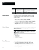
Chapter 3 Installation Figure 3.1 Inserting the USER-PAK Installation / Key card Color CVIM module face USER-PAK Installation/Key card Archive Memory slot Metal Strip Card Label ÇÇÇÇ ÇÇÇÇ ÇÇÇÇ ÇÇÇÇ ÇÇÇÇ ÇÇÇÇ ÇÇÇÇ ÇÇÇÇ ÇÇÇÇ ÇÇÇÇ ÇÇÇÇ ÇÇÇÇ ÇÇÇÇ ÇÇÇÇ ÇÇÇÇ ÇÇÇÇ • Apply the power to the Color CVIM module; this starts the loading sequence. ! ATTENTION: Do not remove power to the Color CVIM module during loading of the USER-PAK option. Doing so may damage the Color CVIM module.
Chapter 3 Installation • Verify that the USER-PAK option is installed by checking the title banner on the monitor after power-up; if the USER-PAK option is installed, there is a message on the banner indicating the presence of the USER-PAK option. • Remove the Installation / Key card from the Archive Memory slot.
Chapter 3 Installation Accessing Setup Mode with USER-PAK Installed Upon installation of the USER-PAK option, access to the setup mode requires the use of a password. The password is entered through a pop-up keyboard which appears when you pick the Setup box, as shown in Figure 3.2. Figure 3.2 Password Entry keyboard Password entry keyboard Note: The password requirement for entry can be disabled; see Chapter 4 for more information on entering the setup mode.
Chapter A–B 4 Getting Started / Using the Security Levels Contents Chapter Objectives . . . . . . . . . . . . . . . . . . . . . . . . . . . . . . . . . . . . . . . . 4–1 Some Questions and Answers about System Security . . . . . . . . . . . . . 4–1 Accessing the Setup Mode . . . . . . . . . . . . . . . . . . . . . . . . . . . . . . . . . . 4–3 Security Levels . . . . . . . . . . . . . . . . . . . . . . . . . . . . . . . . . . . . . . . . . . . 4–4 Changing Passwords . . . . . . . . . . . . . . . . . . .
Chapter 4 Getting Started/Using the Security Levels Why have different security levels available? The different security levels allow for implementation of a hierarchical system of access to and responsibility for the Color CVIM module setup. For instance, a system “administrator” can be designated; this person would have access to the ADMINISTRATOR level.
Chapter 4 Getting Started/Using the Security Levels Accessing the Setup Mode After USER-PAK installation, accessing the setup mode requires entry of a password (unless security has been turned off – see “Setting Security ON/OFF” later in this chapter). Figure 4.1 Password entry keyboard To enter the setup mode from run mode or standby mode (see Figure 4.1, page 4 – 3): • Pick the Setup box on the runtime display, which causes the password keyboard to appear.
Chapter 4 Getting Started/Using the Security Levels If this happens, simply try entering the password again. You can try as many times as is necessary to correctly enter the password. No Keyboard – Setup Mode entered Directly: If, when you pick the Setup box, the Color CVIM module goes directly to setup mode, this indicates Security has been turned OFF (see “Setting Security ON/OFF” later in this chapter to display the password entry keyboard with security OFF).
Chapter 4 Getting Started/Using the Security Levels As shown in Table 4.A, the ADMINISTRATOR level allows access to all the USER-PAK option and base Color CVIM functions, including exclusive access to the first four functions listed.
Chapter 4 Getting Started/Using the Security Levels Security Level Indication While in setup mode with the USER-PAK option installed, the icons in the upper right corner of the screen indicate the current security level: “Trash can” icon (Administrator Level) At the ADMINISTRATOR level, the trash can icon appears on the screen. “M” icon (Manager Level) If you have entered the MANAGER level, the letter “M” is displayed. If you have entered the USER level, no security-level icon is displayed.
Chapter 4 Getting Started/Using the Security Levels each level. If the same password is assigned for two or more levels, the password will access the highest level for that password. For example, if a particular password is used for both the ADMINISTRATOR and MANAGER levels, using that password will access the ADMINISTRATOR level. This means, in this case, the MANAGER level will not be accessible.
Chapter 4 Getting Started/Using the Security Levels • Enter the new password, and pick the Ret key. Once you enter the new password, the keyboard prompts you to reenter the password in order to verify: • Enter the new password again and pick the Ret key. If the verification failed, go back to the “Enter the new password” step, and repeat the procedure from that point.
Chapter 4 Getting Started/Using the Security Levels Setting Security ON / OFF The USER-PAK option allows the ADMINISTRATOR to disable security (that is, remove the password requirement) for entry into the setup mode. Below are descriptions of the effects of having Security: ON (enabled) and Security: OFF (disabled): • Security: ON – A password is required for access to the setup mode. Whenever you pick the Setup box, the password keyboard will appear (see “Accessing the Setup Mode” in this chapter).
Chapter 4 Getting Started/Using the Security Levels Lost Passwords – Using the Installation / Key Card The USER-PAK option provides a method to effectively override the password security feature, and enter the setup mode at the ADMINISTRATOR level. This is accomplished through the use of the Installation / Key card. This “key” method of entry is especially important if the password for the administrator level is lost or is otherwise unavailable.
Chapter A–B 5 Modifying the Color CVIM Menus Contents Chapter Objectives . . . . . . . . . . . . . . . . . . . . . . . . . . . . . . . . . . . . . . . . 5–1 Deletion . . . . . . . . . . . . . . . . . . . . . . . . . . . . . . . . . . . . . . . . . . . . . . . . 5–1 Text Modification . . . . . . . . . . . . . . . . . . . . . . . . . . . . . . . . . . . . . . . . . . 5–6 Modifying Color Names . . . . . . . . . . . . . . . . . . . . . . . . . . . . . . . . . . . . . 5–16 Archiving Menu Modifications . . . .
Chapter 5 Modifying the Color CVIM Menus • USER Level – Items marked for deletion do not appear onscreen at this level, and thus are not available to the user. Deletion Procedure Marking an item for deletion involves just a few basic steps (the following steps assume the ADMINISTRATOR level is accessed): • Insert the Setup card into the Archive Memory slot on the Color CVIM module. • Access the appropriate menu(s) so the item to be deleted is currently displayed on the monitor screen.
Chapter 5 Modifying the Color CVIM Menus “Trash can” icon closed (icon is red when closed) Delete function disabled Here are some additional considerations when marking items for deletion: Paired Menu Items: Paired menu items occupying a single line, such as Copy/Paste, and Previous/Next, should be deleted as a pair. Otherwise menu items may overlap when displayed.
Chapter 5 Modifying the Color CVIM Menus Example – Menu Item Deletion Several items on the Define Window menu are marked for deletion, as shown below in Figure 5.1. Figure 5.1 Items marked for deletion “Trash can” icon open Menu Items Marked for Deletion As a result of the menu deletions marked in the example above, a shortened version of the Define Window menu appears at the USER level (see Figure 5.
Chapter 5 Modifying the Color CVIM Menus Figure 5.2 Deleted items do not appear Define Window menu at the User Level (deleted items do not appear). The Cascade Effect If all items except one have been deleted from a menu, and the one remaining menu item has a three dot leader, the “cascade effect” occurs at the USER level. The cascade effect is this: At the USER level, the subsequent menu or function appears in place of the single menu item.
Chapter 5 Modifying the Color CVIM Menus As you can see, the Define Window menu does not appear. In this case, since the P&P Process Win. box is the only item available on the Define Window menu, picking the Define Window menu would activate the P&P Process Win. function. Text Modification The USER-PAK option enables you to modify the text of menu items, and of onscreen messages such as the help messages or the title banner. Note: To modify text, you must be at the ADMINISTRATOR level.
Chapter 5 Modifying the Color CVIM Menus You can use either of two search methods for finding the entry you want to modify: • Dictionary ID – If you know the dictionary ID number of an entry you want to edit, you can use the dictionary ID to find that entry. • Text String – You use the Text String option just like the search feature on a word processor.
Chapter 5 Modifying the Color CVIM Menus • Pick the Ret key; the Color CVIM then searches the entries in its dictionary, in numerical order, for the first entry containing the text string you entered. When you pick the Ret key, one of two results can occur: (1) No dictionary entry is found to contain the text you entered; the Status: box returns the message Sub-text Not Found. If this happens, try entering a different string.
Chapter 5 Modifying the Color CVIM Menus Dictionary ID Search To use the Dictionary ID method for accessing an entry to modify, follow this general procedure: • First, pick the Dictionary ID box on the Search Method menu to access the ID entry keyboard. The keyboard’s display area includes two fields, Dictionary ID: and Status: • Enter the dictionary ID number of the entry you want to edit. Your entry appears in the Dictionary ID: field in the keyboard display (see Figure 5.6). Figure 5.
Chapter 5 Modifying the Color CVIM Menus • The New Text: entry listed may not be the specific entry you want to change. If it is not, you can either: (1) Enter a different dictionary ID number, or (2) Pick the Find Next: box, which increments the dictionary ID number, and displays the text string for that ID number. Repeat until the specific entry you want to modify is located. Figure 5.
Chapter 5 Modifying the Color CVIM Menus Figure 5.8 Editing text Left / Right Arrows ← → Left/right arrows: Use to move cursor on the same line. For some dictionary entries, such as help messages, all of a line cannot be displayed at once, so you must use the right arrow initially to display the remainder of the line. Figure 5.
Chapter 5 Modifying the Color CVIM Menus Note: If you modify the text of a menu item which has multiple lines (such as the runtime display options menu available during run mode), use the EOL character to create enough lines to account for all the lines in the menu item, in order to have the background color filled in for all lines (even if some lines have no text). For example, the All Tools menu item on the runtime menu contains two lines.
Chapter 5 Modifying the Color CVIM Menus To restore all the original menus and text, or load previously stored modifications, see “Archiving Menu Modifications” later in this chapter. Here are some additional considerations when editing text: Multiple Menu Usage of a Dictionary Entry: In some cases, the same dictionary entry is used in more than one menu. Modifying the entry will affect all menus containing that entry.
Chapter 5 Modifying the Color CVIM Menus Other Restrictions: Menu items which are a part of installed software options (other than the USER-PAK option) are not listed among the dictionary entries, and will not be located when you search for text, nor will the text in the title banner which identifies the Color CVIM module firmware series and revision number, and the installed options. Thus these items cannot be edited.
Chapter 5 Modifying the Color CVIM Menus • Pick the Ret key. The Status: field displays the message Dictionary Entry Changed. Having changed the dictionary entry, when you next display the runtime Display menu, the Result Page box will be changed to read Gage Results. Example 2: We want to change the Envir/Cam→ System→ Units menu item, CM, to MM to reflect the actual range of measurements in our inspections (see Figure 5.11). Figure 5.
Chapter 5 Modifying the Color CVIM Menus • Edit the entry to read MM and pick the Ret key. The Status: field displays the message Dictionary Entry Changed. Having changed the dictionary entry, when you next display the Envir/Cam→ System→ Units menu, the CM item will be changed to read MM. Note: The selected Units entry also appears in the Learn box on the Gage menu, when you select Learn for a Gage set to Linear operation (see Figure 5.12, page 5 – 16). Figure 5.
Chapter 5 Modifying the Color CVIM Menus Select Display Options→Modify Color Name to open the keyboard display. Then edit the color name following the conventions described in the proceeding section. The color name will change on the menu when you press the Ret key. Refer to Figure 5.13 for an example. You can change the names of other colors without closing the keyboard display by selecting Previous or Next until the desired color name appears in the Color menu.
Chapter A–B 6 Creating Custom Serial Port Messages Contents Chapter Objectives . . . . . . . . . . . . . . . . . . . . . . . . . . . . . . . . . . . . . . . . Some Questions and Answers about Custom Serial Port Messages . . . Creating Custom Serial Port Messages . . . . . . . . . . . . . . . . . . . . . . . . . Defining the Serial Port . . . . . . . . . . . . . . . . . . . . . . . . . . . . . . . . . . . . . RS-232 Port Connections and Configuration . . . . . . . . . . . . . . . . . . . . .
Chapter 6 Creating Custom Serial Port Messages How many strings can be defined? The Color CVIM module can store up to 340 strings, depending on how much of the Color CVIM module’s memory is used for other purposes. Can the custom serial port messages coexist with the standard RS-232 port communications with a host device? The custom serial port messages may interfere with the transmission of the response to a command from an RS-232 device.
Chapter 6 Creating Custom Serial Port Messages Basic Steps for Creating Custom Serial Port Messages To create a custom serial port message: • Insert the Setup card into the Archive Memory slot on the module. • Pick Envir/Cam → Config. Output to display the Config. Output menu; this may display a viewport (if a viewport is currently selected). Figure 6.1 Accessing the Config. Output menu Serial Port Selected Config.
Chapter 6 Creating Custom Serial Port Messages Figure 6.2 Selecting the string to be defined String 1 selected Previous / Next boxes – Pick the Enter String Text box to display the string entry keyboard. Using the string entry keyboard, you enter specific string “elements” – literal text, and/or codes of various types – for the string (see Chapter 8 for more information on elements of string text). Figure 6.
Chapter 6 Creating Custom Serial Port Messages Defining Strings Select the Define String box in order to access these features (see Figure 6.4): • Transmit Now – Select this item to immediately transmit the string over the serial port. • Event – Select this item to define the type of event that triggers the transmission of the string. See Chapter 8 for more information.
Chapter 6 Creating Custom Serial Port Messages Figure 6.5 Using the Transmit Now box Define String box Transmit Now box When you pick the Transmit Now box, the transmitted string will not contain any results data, since no inspection has been completed. Therefore any data fields in the transmitted string are filled with zeros (0). Also, the string will be repeated according to the defined Repeat String parameters.
Chapter 6 Creating Custom Serial Port Messages The Define Serial Port menu consists of two items: • Erase Port Data • Buffer: Wait/No Wait Erase Port Data Picking the Erase Port Data box permanently removes all defined strings from the selected serial port. Note: Do not pick this box if you value any portion of your serial port strings or parameters.
Chapter 6 Creating Custom Serial Port Messages Figure 6.7 The Buffer box Buffer box Picking the Buffer box toggles the setting between Buffer: Wait and Buffer: No wait. Buffer: Wait The two Buffer box settings are described below: • Buffer: Wait – With Buffer: Wait selected, the Color CVIM transmits your custom serial port messages with priority over inspection triggers.
Chapter 6 Creating Custom Serial Port Messages The Buffer: No wait setting imposes a message size restriction. Due to the size of the internal buffer, the combined length of all serial messages to be transmitted for a single inspection must be no greater than 128 bytes; serial messages with a combined length greater than 128 bytes will not be transmitted when Buffer: No wait is selected.
Chapter 6 Creating Custom Serial Port Messages • Pick the RS-232 A or RS-232 B box, as appropriate, to display the Protocol and Baud Rate menus. – Pick the ASCII box on the Protocol menu. – Pick the appropriate baud rate on the Baud Rate menu to match the baud rate of the connected device. Figure 6.8 Selecting the serial communication parameters ASCII protocol selected Baud rate selected Equipment Connections The Color CVIM module serial ports are accessible through the I/O Interface box – Catalog No.
Chapter A–B 7 Creating Custom Runtime Displays Contents Chapter Objectives . . . . . . . . . . . . . . . . . . . . . . . . . . . . . . . . . . . . . . . . 7–1 Some Questions and Answers about Custom Runtime Displays . . . . . . 7–1 Initial Setup: Selecting and Defining the Viewport . . . . . . . . . . . . . . . . 7–4 Defining Text and Tool Viewport Contents . . . . . . . . . . . . . . . . . . . . . . . 7–14 Defining Graph Viewports . . . . . . . . . . . . . . . . . . . . . . . . . . . . . . . . . . .
Chapter 7 Creating Custom Runtime Displays Figure 7.1 Example Custom Runtime Display How do you create custom runtime displays? You create custom runtime displays using the Config. Output feature, which becomes available on the Envir/Cam menu with the USER-PAK option installed (Note: The Setup card must be inserted in the Color CVIM Archive Memory slot prior to opening the Envir/Cam menu, to allow access to the Config. Output feature). With the Config.
Chapter 7 Creating Custom Runtime Displays You can select specific colors for the contents in your displays, or you can color code them based on corresponding tool results. There are many more ways of further defining displays which afford a great variety of display effects. How do you determine when a viewport is displayed? In defining a viewport, you also select the display page type and page number of that viewport when it is displayed. You can define a viewport so it replaces a normal runtime display.
Chapter 7 Creating Custom Runtime Displays Initial Setup: Selecting and Defining the Viewport This section describes the initial steps to use in defining a viewport. To define a viewport: • Insert the Setup card into the Archive Memory slot on the Color CVIM module. • Pick the Envir/Cam → Config. Output boxes to display the Config. Output menu; this also displays the viewport, if a viewport is currently selected (see Figure 7.2). Figure 7.
Chapter 7 Creating Custom Runtime Displays Tool Display Setting: With the Envir/Cam→ System→ Tool Display: box set to ON, all viewports are displayed which have an assigned display page and number in common with the currently selected viewport. With Tool Display: box set to OFF, only the current viewport is displayed (see “Selecting Display Pages and Page Numbers” in this chapter). • Pick the Define Viewport . . . box to access the Define Viewport menu (see Figure 7.3). Figure 7.
Chapter 7 Creating Custom Runtime Displays Selecting the Viewport Type Using the Type box on the Define Viewport menu, select one of three types of viewport – Text, Tool, or Graph – which are briefly described below: • Text – The Text viewport allows you to display literal text, or to display tool results, or other data. Text viewport contents (defined by string text) are positioned within the viewport area.
Chapter 7 Creating Custom Runtime Displays makes the Tool viewport type preferable if the viewport strings are defined so that the displayed content can change in position each time it is displayed. Tool string color is limited to four choices; Text viewport strings can be set to any of eight different choices of color. Tool viewport contents are displayed “beneath” Text viewport displays, and base Color CVIM runtime displays, if these displays occupy the same screen.
Chapter 7 Creating Custom Runtime Displays Using Pick & Place To position the viewport on the monitor, and thus determine where it is displayed on the screen during runtime, you use the Pick & Place function (Pick & Place is disabled for Tool viewports; the Tool viewport “border” is the same as the monitor screen border). The procedure for positioning viewports is identical to that for placing windows – with Pick & Place selected, handles appear on the viewport border and center.
Chapter 7 Creating Custom Runtime Displays Figure 7.6 Activating the Pick & Place function Viewport handles appear when Pick & Place function is activated Menu Removal icon Transparent menus Pick & Place box For example, to place a viewport so it appears in the upper right quarter of the screen during runtime, you would place it in that position during setup (see Figure 7.7, page 7 – 10).
Chapter 7 Creating Custom Runtime Displays Figure 7.7 Example of placing the viewport Viewport placed in upper right corner during setup. Pick & Place box Here are additional considerations when selecting and positioning viewports: Position Limitation: The bottom portion of the screen (about 15% or so) is reserved for the runtime menus, and you will not be able to drag a Text or Graph viewport border into this region.
Chapter 7 Creating Custom Runtime Displays Figure 7.8 Example of viewport border and background colors Border Background Display Contents The procedures for selecting both the border and background colors are identical: • Pick the appropriate menu item (either Border or Backg.), which displays a Color Selection menu. • Pick a box on the Color Selection menu for the desired color. Figure 7.9 Example of viewport border and background colors Color Selection menu Backg.
Chapter 7 Creating Custom Runtime Displays Selecting Display Pages and Page Numbers Use the Display Pages and Page # items in combination to determine how to access the viewport during runtime. You assign the viewport to the display type(s) and the specific page number(s) during setup. Then, during run mode, use the Display menu, and Page ↑ and Page ↓ boxes, on the run mode screen to access the page type and number, and thus show the display. For example, you can assign a viewport to Results Page 2.
Chapter 7 Creating Custom Runtime Displays Figure 7.10 Example of viewport border and background colors Display Pages menu Selected menu item Display Pages box To select the Page #: • Pick the Page # box on the Define Viewport menu to open the Page Numbers menu (see Figure 7.11). • Pick the appropriate box(es) on the Page # menu. Figure 7.
Chapter 7 Creating Custom Runtime Displays Erase Port Data Picking the Erase Port Data box permanently removes all defined strings from the selected viewport, and also resets all the Define Viewport parameters to default settings. Note: Do not pick this box if you value any portion of your viewport strings and current Define Viewport parameter settings.
Chapter 7 Creating Custom Runtime Displays Defining Text and Tool Viewport Contents This section discusses how to define Text and Tool viewport contents – both types are discussed together because the procedure for defining the contents for the two types is identical. Figure 7.
Chapter 7 Creating Custom Runtime Displays Figure 7.14 Selecting the viewport string String 1 selected Previous box Next box If you pick and hold the Next or Previous box, the string selection increments continuously. Note: All strings for a selected viewport are displayed on the screen. The currently selected string is displayed in red, others are green. Portions of red (current) and green (other) strings which overlap are displayed in yellow.
Chapter 7 Creating Custom Runtime Displays Using the Define String Menu To further define a string you are creating, select the Define String box to display the Define String menu (see Figure 7.16, page 7–15). Note: The Define String box is disabled until at least one character of string text has been entered for the selected string (see Chapter 8 for information on entering string text).
Chapter 7 Creating Custom Runtime Displays • Pick the Dir box to toggle the selection between Right and Down. Figure 7.17 Selecting the string direction Dir box (with Down selected) String displayed in Down direction Setting the Dir box to Down causes the characters of the string to be displayed downward in a vertical column (as shown above), rather than Right (across the screen from left to right), which is the default setting.
Chapter 7 Creating Custom Runtime Displays Figure 7.18 Selecting the string direction Double Width string Single Width string Width box Setting the Width box to Double causes the characters of the string to be doubled in size when displayed. This is useful when you want certain strings to be prominent, or if you need larger characters for better readability. Selecting String Color You further define appearance of the string by selecting the color. You do this using the Color menu item.
Chapter 7 Creating Custom Runtime Displays Figure 7.19 Selecting the string direction Color Selection menu Color box Here are additional considerations when selecting string colors: Override for String Color: The string color can be changed using the change color codes or conditional color indicator within the string text, each of which will override the color selected through the Color Selection menu (see “Change Color Codes” and “Conditional Color-coding” in Chapter 8).
Chapter 7 Creating Custom Runtime Displays Figure 7.20 Placing the string Handle appears when Pick & Place function is activated To activate the Pick & Place function: • Pick the Pick & Place box on the Define String menu; a small rectangular “handle” appears in the middle of the string. • Pick and “drag” the string handle to reposition the string (refer to the pick & place procedures in the Color CVIM User’s Manual for more information).
Chapter 7 Creating Custom Runtime Displays Defining Graph Viewports This section discusses how to define Graph viewports. Graph viewports provide the capability to display in real time, and in graph form, the results from gages, windows, and/or formulas. Graph viewport contents are displayed during run mode in a bordered area, for which the border, background, and graph colors are user-defined.
Chapter 7 Creating Custom Runtime Displays When the Graph viewport is displayed during run mode, the defined variables are plotted from left to right; plotted variables are either line or dot style (as defined), and the leading edges of the plotted variables are emphasized by the “current position indicator,” a vertical line spanning the viewport.
Chapter 7 Creating Custom Runtime Displays Figure 7.22 Selecting the variable Variable 1 selected Previous box Next box Defining the Variable After selecting a specific variable, you next define the variable using the Define Graph Var. menu. To display the Define Graph Var. menu: • Pick the Define Variable box. Figure 7.23 Accessing the Define Graph Var. menu Define Variable box Define Graph Var.
Chapter 7 Creating Custom Runtime Displays Setting the Style You pick the Style box to enable/disable the variable and the remainder of the menu, and also to set the “style” of the variable. Figure 7.24 Selecting the variable style Style box, with Line Graph selected Note: When the Define Graph Var. menu is initially displayed, the Style box is set to Disabled, and the remainder of the menu items are disabled.
Chapter 7 Creating Custom Runtime Displays Figure 7.25 Examples of variable styles Graph Viewport Example Line Graph Example Dot Graph Selecting Variable Color You further define appearance of the variable by selecting the Color; this is the color of the line or dot graph created during run time. To select the color for a graph variable (Figure 7.26, page 7 – 26): • Pick the Color menu item, which displays a Color Selection menu. • Pick the box for the desired color.
Chapter 7 Creating Custom Runtime Displays To select a gage, window, or formula as the variable tool: • Pick the appropriate box on the Define Graph Var. menu – Gage, Window, or Formula. This causes the calculator keypad to appear. • Use the calculator pad to enter the number for a specific gage, window, or formula. Note: You must have the MATH-PAK option (Cat. No. 5370-MPKC) installed in order to successfully use any Formula selection. Figure 7.
Chapter 7 Creating Custom Runtime Displays Figure 7.28 Accessing the Define Graph menu Define Graph box Define Graph menu Upper limit box Lower limit box Defining the Viewport Limits – Upper and Lower The Upper and Lower boxes on the Define Graph menu enable you to set the range for the variables plotted within the viewport. The Upper limit sets the maximum value that the viewport can plot, and corresponds to the top of the Graph viewport.
Chapter 7 Creating Custom Runtime Displays Figure 7.
Chapter 7 Creating Custom Runtime Displays Valid Range: The valid range for the Upper and Lower limits are –32767 to 32767, and the difference between the two limits must not exceed 32767. If you try to enter a number which is not valid, such as a Lower limit value which is higher than the current Upper limit, the calculator pad will flash the message – Value Out of Range. Defining the Event For each Graph viewport you define, you must specify the Event.
Chapter A–B 8 Defining Strings for Serial Ports and Viewports Contents Chapter Objectives . . . . . . . . . . . . . . . . . . . . . . . . . . . . . . . . . . . . . . . . Entering (or Modifying) String Text . . . . . . . . . . . . . . . . . . . . . . . . . . . . Valid Elements of String Text . . . . . . . . . . . . . . . . . . . . . . . . . . . . . . . . . Defining the Event . . . . . . . . . . . . . . . . . . . . . . . . . . . . . . . . . . . . . . . . . Using Repeat String . . . . . . . . . . . . . . .
Chapter 8 Defining Strings for Serial Ports and Viewports • Enter or modify the string text for the selected string using the string entry keyboard. The characters you select appear in the keyboard display. • Pick the Ret key when finished entering or modifying text, which enters the string into memory. String Syntax: When you pick the Ret key, the Color CVIM module checks for syntax errors; one of two messages is displayed beneath the string text (see Figure 8.2). Figure 8.
Chapter 8 Defining Strings for Serial Ports and Viewports String Numerical Order: Strings within a given serial port or viewport are processed for each inspection in numerical order, so that lower-numbered strings are transmitted (displayed) before higher-numbered strings which are transmitted (displayed) for the same inspection.
Chapter 8 Defining Strings for Serial Ports and Viewports Figure 8.3 Example of literal text entry Quotation marks Literal text entry, as it is displayed on the keyboard String entry keyboard You can enclose a number of spaces in quotes to provide spacing between fields within the message, as shown below: Spaces included in quotes Data code Valid Characters for Literal Text: Any character(s) that you enclose in quotes will be sent as literal text, except the quotation mark ( ” ) character.
Chapter 8 Defining Strings for Serial Ports and Viewports Table 8.A (pt. 1 of 3) Data Codes Data Code➀ Description of field Subcodes (.s)➀ Gn.0 Gage measurement value (# of pixels, # of edges, etc.) Gn.1 Pass/fail condition for warning range (1 = pass, 0 = fail). Gn.2 Pass/fail condition for fault range (1 = pass, 0 = fail). Gn.s (n = 1 to 64) (s = 0 to 9) Gn.3 Second coordinate value (Y coordinate for X Position gage; X coordinate for Y Position gage). Gn.4 Number of faults detected.
Chapter 8 Defining Strings for Serial Ports and Viewports Table 8.A (pt. 2 of 3) Data Codes Description of field Data Code➀ Subcodes (.s)➀ RLn.0 X coordinate value of edge position on reference line. RLn.s (n = 1 to 3) (s = 0 to 4) RLn.1 Y coordinate value of edge position on reference line. RLn.2 Pass/fail condition for reference line (1 = pass, 0 = fail). (For Ref. Lines) RLn.3 Theta from a reference line configured for “X–X then Y” or “Y–Y then X” rotation compensation. RLn.
Chapter 8 Defining Strings for Serial Ports and Viewports Table 8.A (pt. 3 of 3) Data Codes Data Code➀ Description of field Subcodes (.s)➀ M.0 The total triggers (includes missed triggers). M.1 The total missed triggers. M.2 Number of master range faults. M.3 The name of the configuration. L.0 Light probe brightness value for red channel. L.1 Light probe brightness value for green channel. L.2 Light probe brightness value for blue channel. L.
Chapter 8 Defining Strings for Serial Ports and Viewports Special Characters: N, /, %, # These four characters have special functionality within the string text: N / % # – the newline character – the character code indicator – the formula indicator – the index character The N (newline) character Serial Ports: Place the letter N (upper or lower case) in the string to transmit both the ASCII carriage return [CR] and line feed [LF] characters.
Chapter 8 Defining Strings for Serial Ports and Viewports / Character Code Indicator Serial Ports: You can transmit any character from the ASCII character set by inserting the character code indicator, which takes this form: /cc where cc (character code) is a number from 0-255 which specifies the character (see Appendix B for a listing of the available characters and their codes).
Chapter 8 Defining Strings for Serial Ports and Viewports % Formula Indicator You can use the result from a formula for a character code, color code, or line drawing parameter instead of entering a fixed numeric value. To do this, enter the formula indicator in the place of the numeric value within the respective code. The formula indicator takes this form: % fn where fn is a number from 1-56 which specifies the respective formula result (you must have installed the MATH-PAK option, Cat. No. 5370–CMPK).
Chapter 8 Defining Strings for Serial Ports and Viewports You can use the # (index) character in two ways: • Place the # in the string to take the place of the tool number designation in a data code – for example, G#, or W#. • Place the # by itself in the string to transmit or display the current index number. You can, at your option, specify the format of the index “field” in the output.
Chapter 8 Defining Strings for Serial Ports and Viewports Field Formatting Codes You can, at your option, specify the format of the contents of any numerical field, that is, fields in the displayed or transmitted strings which correspond either to tool results (or other data), or to the index (#) number. You specify field format by placing a field formatting code in parentheses immediately following the data code (or index character) in the string you are defining.
Chapter 8 Defining Strings for Serial Ports and Viewports Examples: Assume window 1 result = 1234: This code transmits (or displays) this field: W1 _ _ _ _ _1234 (default format is 9 places, right justified) W1(5) _ 1234 W1(3) 123 (result is truncated) W1(0) (no field transmitted or displayed) Examples: Assume formula 1 result = 123.45: * This code transmits (or displays) this field: F1(5) 123.4 (result is truncated) * F1(6) 123.45 F1 _ _123.
Chapter 8 Defining Strings for Serial Ports and Viewports W1(–08) 12340000 Examples: Assume formula 1 result = 123.4 This code transmits (or displays) this field: F1(08) 0123.400 F1(–08) 123.4000 (x.d) The x indicates the field width, while the d value specifies the maximum number of decimal places to be present in the field. Note that the d value is only effective if decimal places are actually part of the tool result.
Chapter 8 Defining Strings for Serial Ports and Viewports (2) for index fields. That is, the field width is 2 characters; the contents of the field are right justified. Conditional Color-coding You can color-code any tool value based on the pass/warn/fail status of the respective tool result status. You do this by placing the conditional color code indicator (the ! symbol) after the particular data code.
Chapter 8 Defining Strings for Serial Ports and Viewports displayed in one of the three conditional colors (green, yellow, or red) depending on the status of the result. Draw Line Codes You can draw lines within a viewport (either Text or Tool type).
Chapter 8 Defining Strings for Serial Ports and Viewports (0, 0) Starting point Viewport border (10, 20) Line drawn End point (40, 60) The end point x- and y-coordinates in this example would be (40, 60). The x-coordinate of the end point (40) is obtained by adding the dx value (30) to the starting point x-coordinate value (10). The y-coordinate of the end point (60) is obtained by adding the dy value (40) to the starting point y-coordinate value (20).
Chapter 8 Defining Strings for Serial Ports and Viewports Cursor Positioning with Draw Line Codes Any string content that follows the draw line parameters in the string will be displayed beginning at the end point of the line previously drawn. This is because draw line parameters set the current “cursor position” for the string. The cursor position is the point at which the next field in the string will be displayed, or the next line in the string will be drawn.
Chapter 8 Defining Strings for Serial Ports and Viewports Using the * Symbol The * symbol can be used as a parameter for either or both of the starting point coordinates (the x and y values). The * symbol causes the respective x or y value to be determined by the current cursor position. For example, this code: D*,* 50,0 causes a horizontal line to be drawn, 50 pixels in length, with the starting point determined by the current cursor position.
Chapter 8 Defining Strings for Serial Ports and Viewports Plot Line Codes You can use plot line codes to draw lines within a viewport (either Text or Tool type), just as you would use draw line codes (refer to the previous section for information on draw line codes).
Chapter 8 Defining Strings for Serial Ports and Viewports The change color code changes the color for the portion of the string displayed after the code. More than one change color code can be placed within a string. Table 8.B Color Codes for Strings No.
Chapter 8 Defining Strings for Serial Ports and Viewports Summary of Codes and Indicators Table 8.C provides a summary of the special characters and indicators for defining strings. Table 8.C Special Characters and Indicators for Defining Strings Character / Indicator Descriptive Term Usage ”” Literal Text The quotation marks when placed around characters in the string text, specify that text is to be transmitted (or displayed) literally.
Chapter 8 Defining Strings for Serial Ports and Viewports Defining the Event For each string you define, you can specify the “event.” In specifying the event, you are defining the conditions which must be met, upon completion of an inspection, in order for a given string to be transmitted. For example, you can specify that the string is always transmitted (or displayed) upon completion of an inspection (this is the default setting).
Chapter 8 Defining Strings for Serial Ports and Viewports After selecting the event source, you pick the source condition box (the topmost box) to specify the condition of the selected event source (master range, tool, or formula). During run mode, upon completion of an inspection, the Color CVIM checks the specified event source to see if it has met the specified source condition.
Chapter 8 Defining Strings for Serial Ports and Viewports Value Out of Range: If you try to enter a number which is not valid, such as a gage number 65 (there are only 64 gages), the calculator pad will flash the message – Value Out of Range. If this happens, pick an appropriate number, and then pick the Enter key again. Figure 8.5 Using the calculator pad for selecting the event source Calculator Pad Gage box Selecting the Source Condition After specifying the event source (Master Range, Gage, etc.
Chapter 8 Defining Strings for Serial Ports and Viewports • With a Gage, Window, or Formula selected, the options are: – Print if Enabled – String sent at the completion of each inspection, as long as the specified event source (tool or formula) is enabled. – Print on PASS – String sent only if the event source (tool or formula) passes the inspection. – Print on WARN – String sent only if the result for the event source (tool or formula) exceeds warning range limits but does not fail.
Chapter 8 Defining Strings for Serial Ports and Viewports Figure 8.6 Using the calculator pad for selecting the interval Calculator Pad Print Every ... box To set the interval (see Figure 8.6): • Pick the Print Every (interval) box. • Select the interval using the calculator pad.
Chapter 8 Defining Strings for Serial Ports and Viewports Using Repeat String The Repeat String feature enables the Color CVIM module to repeat a particular string multiple times for the same event (see “Defining the Event” in this chapter). This is accomplished through the use of an “index” number, which is incremented through a range of values – you define this range using the Repeat String menu. Figure 8.
Chapter 8 Defining Strings for Serial Ports and Viewports The string is sent for each index value, until the index value exceeds the End value. For example, to repeat a string 5 times, you can set the Start value to 1, the End value to 5, and the Increment to 1. The index will increment through values 1 to 5. Or, you can set the Start value to 6, the End value to 10, and set the Increment to 1, so the index will increment from 6-10, and so forth.
Chapter 8 Defining Strings for Serial Ports and Viewports Figure 8.8 Using the calculator pad for selecting the Repeat String parameters Calculator Pad End: box Value Out of Range: If you try to set a parameter to a value which is not valid, such as a Start value higher than the End value, or a value out of the 1-127 range, the calculator pad will flash the message – Value Out of Range.
Chapter 8 Defining Strings for Serial Ports and Viewports Index character as part of data code Index character alone The resulting transmission for the inspection consists of five strings, one for each increment of the index (1-5), where the gage results are transmitted for gages 1-5, respectively: Gage Gage Gage Gage Gage 1 = 205 [CR] [LF] – (where current index is 1) 2 = 30 [CR] [LF] – (current index is 2) 3= [CR] [LF] – (current index is 3) 4 = 110 [CR] [LF] – (current index is 4) 5 = 20 [CR] [LF] –
Chapter 8 Defining Strings for Serial Ports and Viewports Note that the newline character (n) placed at the end of the string causes a carriage return and line feed to be transmitted at the end of each line: Newline Character Transmitted String: Gage 1 = 205 [CR] [LF] Gage 2 = 30 [CR] [LF] . . . etc. Viewports: The “Text and Tool Viewport String Examples” section in this chapter provides an example of using the repeat string feature, and the (N) newline and (#) index characters.
Chapter 8 Defining Strings for Serial Ports and Viewports Custom Serial Port Message Example This section provides an example of a serial port message string, for the purpose of demonstrating the use of string elements, and the definition of the Event. For this example, we want to transmit the results of the two gage measurements, and also to transmit the results only if the inspection fails. First, determine the format.
Chapter 8 Defining Strings for Serial Ports and Viewports Data Codes – Using a data code results in the transmission of a field containing corresponding data. The example includes two data codes, g1 and g2, which cause the transmission of the gage 1 and gage 2 results (109 and 112), respectively.
Chapter 8 Defining Strings for Serial Ports and Viewports transmitted only when the master range fails – that is, when the inspection fails (see Figure 8.9). Figure 8.
Chapter 8 Defining Strings for Serial Ports and Viewports Text and Tool Viewport Examples This section examines the example viewport displays shown below, and describes how, for the Text and Tool viewport portions of the display, various text strings were used to achieve the display contents. Figure 8.
Chapter 8 Defining Strings for Serial Ports and Viewports Example 1 – Creating a Special Character The labels for the Graph viewport (0→ and 63→ ) were created using Text viewport strings. Figure 8.11 Example of special characters in a runtime display Example 1 Generating the arrow character required the used of a character code within the string text – that is, the / character followed by a number representing the character. The string text for 0→ is shown below.
Chapter 8 Defining Strings for Serial Ports and Viewports Example 2 – Using the Change Color Code The Graph viewport, which plots the results of window 1 and 2, is headed by the actual result values for the two windows. These two window results were created by a single viewport string, and each result is colored to match the respective window result being plotted. Generating the change in color within the string required the used of a color code within the string text. Figure 8.
Chapter 8 Defining Strings for Serial Ports and Viewports Example 3 – Using the Draw Line Code A draw line code was used to draw the horizontal line separating the display title (“Acme . . .”) from the rest of the viewport. Figure 8.14 Example of drawing a line in a custom runtime display Example 3 Shown below is the string text used to create the horizontal line. Recall that the draw line code follows the format Dx,y dx,dy.
Chapter 8 Defining Strings for Serial Ports and Viewports Example 4 – Using Repeat String and # (Index) Character The first column in the viewport display (Gage 1:, Gage 2:, etc.) was created using a single viewport string, along with the Repeat String feature. Figure 8.15 Example of using repeated strings in custom runtime displays Example 4 Here are the elements of the text used to create the string: • Literal text (enclosed in quotes) is used to display the word Gage and the “:” (colon).
Chapter 8 Defining Strings for Serial Ports and Viewports Setting the Repeat String Parameters Recall that the Repeat String feature allows you to repeatedly display a string. This is accomplished through the use of an “index” number, which is incremented through a range of values – you define this range using the Repeat String menu. In order to use the Repeat String feature, you must define the range (that is, the Start, End, and Increment values) using the Repeat String menu: Figure 8.
Chapter 8 Defining Strings for Serial Ports and Viewports The Color CVIM module thus displays the string for each index value, until the index value exceeds the End value. If the # character is included in the repeated string, the current index value replaces the # character in the string. In our example, to display the string 5 times, and include the numbers 1-5 in the five strings, respectively, we set the Start value to 1, the End value to 5, and the Increment to 1.
Chapter 8 Defining Strings for Serial Ports and Viewports • Format codes are added to each data code. The format code (7.3) is added to the data code S#.3 (the mean), setting the width of the displayed data field to seven places, and limiting the decimal portion of the field to three places. The format code (7.4) is added to the data code S#.4 (the standard deviation), setting the field width to seven places, and limiting the decimal portion of the field to four places.
Chapter 8 Defining Strings for Serial Ports and Viewports current index number is inserted, designating the specific tool type and number for the mean and standard deviation. Keep in mind that we are displaying the mean and standard deviation for gages 1-5. According to the data code table (see “Data Codes” this chapter), the code S9.3 will display the mean for gage 1, the code S10.3 will display the mean for gage 2, etc. Likewise, the code S9.4 will display the standard deviation for gage 1, the code S10.
Chapter 8 Defining Strings for Serial Ports and Viewports master range passes (the part passes). Otherwise, once PART REJECTED is displayed, it remains on screen, even though parts are not failing inspections. The string text for the PART REJECTED message is simply this: In order to display the message only when the master range fails, we need to set the Event menu so that Master Range and Print on FAIL are selected: Figure 8.
Chapter 8 Defining Strings for Serial Ports and Viewports Example 7 – Using Formulas and Plot Line Codes Recall that it is possible to draw or plot lines, and/or position strings through the use of draw line or plot line codes, and that it is possible to use the results of formulas as draw/plot line parameters. The Tool viewport string in our example display provides a case in which tool results are used to plot lines and position strings within the display. Figure 8.
Chapter 8 Defining Strings for Serial Ports and Viewports point of the line) is %2, indicating the y-coordinate is taken from formula 2. The formula 2 result is defined, in this case, as the y-coordinate of the edge detected by the reference line. Thus the line’s starting point, based on the two formula results, is located at the corner of the part. As the part position changes from inspection to inspection, the starting point of the line moves accordingly.
Chapter A–B 9 Using Copy and Paste Contents Chapter Objectives . . . . . . . . . . . . . . . . . . . . . . . . . . . . . . . . . . . . . . . . Using Copy and Paste . . . . . . . . . . . . . . . . . . . . . . . . . . . . . . . . . . . . . .
Chapter 9 Using Copy and Paste • Select the destination – Pick the Next or Previous box as necessary to set the number to the destination – the component (tool, viewport, serial port, or string) which which will receive the settings from the source. • Pick the Paste box. The settings are automatically copied from the selected source to the currently selected component (destination).
Chapter 9 Using Copy and Paste Figure 9.2 The Copy and Paste boxes for a window Window menu Window 1 selected • Pick the Copy box to select window 1 as the source. The Paste box will display the number of the source window – in this case, the box reads Paste 1, for window 1. • Pick the Next box to select window 2. Figure 9.3 Selecting the Paste destination Window 2 selected • Pick the Paste box to copy the settings from window 1, the source tool, to window 2.
Chapter 9 Using Copy and Paste • Pick the Previous or Next boxes as required to select viewport 1. • Pick the Copy box to select viewport 1 as the source. The Paste box will display the number of the source viewport – in this case, the box reads Paste 1, for viewport 1 (see Figure 9.4, page 9 – 4). • Pick the Next box to select the destination viewport – viewport 2. • Check the Paste box. If the Paste box is disabled, viewport 2 has at least one string for which text has been entered.
Chapter 9 Using Copy and Paste • Pick the Paste box to place the source contents into the destination string. The Paste box retains the source string listing (1/2, in this case) until you close and reopen the Config. Output menu. The source string listing is updated if and when you select a different source string. Figure 9.
Chapter A–B 10 Loading Color CVIM / USER-PAK Configurations Contents Chapter Objectives . . . . . . . . . . . . . . . . . . . . . . . . . . . . . . . . . . . . . . . . 10–1 Loading Color CVIM / USER-PAK Configurations . . . . . . . . . . . . . . . . . 10–1 Checking Available Memory . . . . . . . . . . . . . . . . . . . . . . . . . . . . . . . . .
Chapter 10 Loading Color CVIM / USER–PAK Configurations • Pick the desired feature (Load Config. (Int) or Load Default Config.) on the Archival menu. • Pick the appropriate box (Menus, Viewports / Serial Ports, Inspection, or All CVIM) on the respective menu. Figure 10.1 The Load Config. (Int) menu Archival menu Load Config ( Int ) menu Picking any of the four boxes causes this message to appear: • Pick the same box again to load the configuration.
Chapter 10 Loading CVIM / USER–PAK Configurations In order to load the configuration in this case, you must first adjust your current working configuration to free up the required memory space. The procedure for loading a portion of a configuration will depend on which portion you want to load, and where it is stored.
Chapter 10 Loading Color CVIM / USER–PAK Configurations Checking Available Memory The USER-PAK Menus and Viewports / Serial Ports configuration data is stored in the Color CVIM module in an allotted area of memory that is also used for storing Color CVIM MATH-PAK formulas (refer to the Color CVIM User’s Reference Manual for more information regarding these features). Figure 10.2 Checking available memory Help message Help Icon Config. Output box.
Appendix A–B A Connecting and Using a Mouse Objective With the USER-PAK option installed, the Color CVIM module user has the option of connecting and using a mouse, instead of the light pen, for interacting with the Color CVIM module menus. This appendix describes the hardware requirements and considerations, physical connections, and simple configuration requirements for connecting and using a mouse.
Apppendix A Connecting anfd Using a Mouse Figure A.1 Selecting the Mouse option Mouse selected Crosshairs symbol With Mouse selected, a “crosshairs” symbol appears on the screen. When Mouse is selected, the “crosshairs” symbol indicates the current mouse position relative to the screen contents. The light pen is still active (that is, still in control of the cursor position and item selection) when Mouse is first selected; the mouse device control must be activated in order to use the mouse.
Appendix A Connecting and Using a Mouse Types of Mouse and Trackball Supported The Color CVIM module (with the USER-PAK option installed) supports most serial mouse-type devices (including track balls) which are IBM-PC compatible. Several types of mouse and trackball that can be used with the Color CVIM module are listed below. These lists do not include all types that will work, but the types listed have been tested and found to work.
Appendix A–B B Character Codes This appendix lists the character codes that can be used with the / (character code) indicator to generate special characters within a text string defined for a serial port or viewport (refer to “/ Character Code Indicator” in Chapter 8). Character Code Character Code Character Code Character Table B.
Appendix B Character Codes Serial Port or Viewport Strings 1 Codes Character Code Character Code Character Code Character Code Character Code Character Code Character Code Character Code Character Code Character Code Table B.B Character Codes (Serial Ports and Viewports) 1, 2, 3 Viewport Strings Only 32-127 (left side of Table) represent standard ASCII characters, and are useful for either serial ports or viewports.
Appendix A–B C ASCII Commands for the USER-PAK Option Objective With the USER-PAK option installed, the Color CVIM module recognizes additional ASCII commands through its serial port(s). This appendix lists and describes these additional commands.
Appendix C ASCII Commands for the Color USER–PAK Option When the command is invoked for a viewport string, the specified string is displayed immediately, given the following conditions: • The specified viewport is currently displayed. • For the last displayed inspection, the Event conditions defined for the specified string are true.
Appendix C ASCII Commands for the Color USER–PAK Option Read String Data Command The Read String Data command can be used to obtain the defined attributes and string text of the specified string. The Read String Data command takes this format: >OR, p, s Where: p = number of viewport (or letter of serial port) s = number of string The response from the Color CVIM module takes this format: Ax Cx, text For content definition of the response fields, refer to the Write String Data parameter descriptions.
Appendix C ASCII Commands for the Color USER–PAK Option Write Display Command (Enhancement) The Write Display command, currently available with the base Color CVIM module operating system, is enhanced when the USER-PAK option is installed (refer to the Select Image Displayed command in the Color CVIM Communications Manual). The Write Display command is enhanced to allow the selection of the page number, along with the selection of the display page.
Index A Accessing the setup mode, 3 - 4, 4 - 3 Archiving Text Modifications, 5 - 17 ASCII commands, C - 1 Force print, C - 1 For serial port strings, C - 2 For viewport strings, C - 1 Read string data, C - 3 Suspend / resume serial port output, C - 3 Write display, C - 4 Write string data, C - 2 Attention, notices of, 1 - 2 Audience, intended, 1 - 2 Available memory, checking, 10 - 4 B Buffer, Serial Port, 6 - 7 C Cards, memory Installation / Key, Security, 3 - 3 Installation / key, Lost passwords, Using
Index Defining Strings, 6 - 4 Using Transmit Now, 6 - 5 Entering/Modifying String Text, 8 - 1 Copy and paste, using, 9 - 4 Example of a serial port message string, 6 - 2 Example, 8 - 33 Introduction, 2 - 4 Questions and answers about, 6 - 1 CVIM Module, Restarting, 3 - 3 D Data codes, 8 - 4 Examples Serial port, 8 - 34 Text and tool viewports, 8 - 38, 8 - 42, 8 - 47 Default password, 4 - 7 Lost password, 4 - 10 Define string menu, 7 - 17 Color, Selecting String, 7 - 19 Additional considerations for, 7 - 2
Index In string text, 8 - 10 Example, Text viewport, 8 - 40 As part of data code, 8 - 43 Using an offset with, 8 - 11 Used with repeat string, example, 8 - 30 Text viewport, 8 - 40, 8 - 42, 8 - 43 Installation / Key card Introduction, 3 - 1 Lost passwords, Using the, 4 - 10 Security, 3 - 3 Installing the USER-PAK option, 3 - 1 Intended audience, 1 - 2 Interval Selecting, 8 - 26 Special cases for serial ports, 8 - 27 What the interval is, 8 - 26 K Key Card.
Index S Searching for text, 5 - 6 Dictionary ID, 5 - 7, 5 - 9 Text String, 5 - 7 Security, Setting On/ OFF, 4 - 9 Security levels, 4 - 4 Functions / Features (table), 4 - 4 Indication, 4 - 6 Introduction, 2 - 1 Questions and answers about, 4 - 1 Serial Port Connection and Configuration, 6 - 9 Equipment Connections, 6 - 10 Selecting Serial Port Parameters, 6 - 9 Defining the, 6 - 6 Buffer, 6 - 7 Erase Port Data, 6 - 7 Serial port messages, custom.
Index Toolset selection, Display pages and numbers, Graph viewport, 7 - 30 Trademarks, 1 - 3 Transmit Now, Using, 6 - 5 Type, viewport, selecting.
Allen-Bradley has been helping its customers improve productivity and quality for 90 years. A-B designs, manufactures and supports a broad range of control and automation products worldwide. They include logic processors, power and motion control devices, man-machine interfaces and sensors. Allen-Bradley is a subsidiary of Rockwell International, one of the world’s leading technology companies. With major offices worldwide.