
Instruction Manual Owner's manual

Installing Bulletin 500LC Lighting Contactors
4
Publication 500LC–IN001A–EN–P May 2005
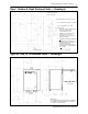
Line and load terminals are reversible. The Bulletin 500LC
Lighting Contactor is UL Listed for use with 60 or 75˚ Cwire.All
power wires should enter enclosure adjacent to the 500LC
terminals. Combination knockouts are provided on Type 1
enclosures. L ine and load connections are supplied with clamp
type terminals. These terminals accept the wire sizes #18–10
AWG Cu. Insert appropriate line and load wires and tighten clamp
screws to 18 inch–pounds.
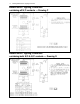
Control Line Connections
Control circuit connections designated L, O, C on the right side are
supplied with clamp type terminals. These terminals accept wire
sizes #18–10 AWG Cu. Simply insert appropriate control wires
and tighten terminal clamp screws to 18 inch–pounds. See the
wiring diagrams.
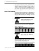
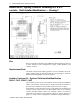
In st all over cu r r en t p r o t ect ive devices
for the contro l circuit in accordance
with app lic able electrical cod es.
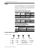
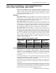
Table D lists the maximum distances and minimum wire sizes that
can be run between a control station and one Bulletin 500LC.
Table D – Control Line Run
Wire Size Maximum Distance (feet) at AC control voltage
(AWG) 120V 240V 277V 347V 480V
14 1,050 3,100 4,100 5,600 8,800
12 1,670 5,000 6,600 9,000 14,000
10 2,650 8,000 10,600 14,000 22,000
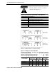
Do not exceed thes e distan ces fo r
proper unit operation.
Table E lists the Bulletin 500LC Lighting Contactor’s coil inrush
current and minimum control circuit fuse sizes.
Table E – Inrush Current / Minimum Fuse
Inrush Current Over Fuse Size (amps RMS) at AC control voltage
Amps 120V 240V 277V 347V 480V
inrush 5.0 2.5 2.2 1.8 1.3
fuse 2.0 1.0 1.0 0.75 0.5