
Instruction Manual Owner's manual

Installing Bulletin 500LC Lighting Contactors
10
Publication 500LC–IN001A–EN–P May 2005
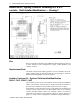
For DC modu les be sure to con nect
terminal 4 to negative (–).
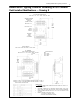
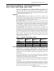
Table G – Connections to Solid–State Control Modules
Module Terminal Connected To
1 not used
2 control station for Mod. 500LC–48CM*, 500LC–49SS*
3
control station for Mod. 500LC–47CM*,
500LC–48SS*, 500LC–49SS*
4 Control Module control voltage*
5 500LC Lighting Contactor control voltage
O pre–connected to O on 500LC Lighting Contactor
C pre–connected to C on 500LC Lighting Contactor
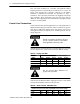
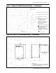
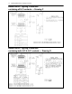
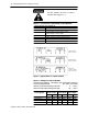
3 WIRE CONTROL
MOD. 500LC–48CM*
2 WIRE CONTROL
MOD. 500LC–47CM*
ST ART–STOP
(FORM 3) CONTROL
MOD. 500LC–49SS*
Figu re 1 Typical labels on co ntrol mod ules
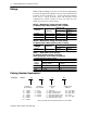
Table H – Ratings for Control Modules
Nominal Input Voltage see Table F, AC voltages are 50/60 Hz.
Control Voltage Range 80...125% of nominal..............
Ambient Temperature Range Operate 0˚...+45˚C..........
Ambient Temperature Range Storage –30˚...+65˚C.........
Control Module
Mod.
500LC–47CM*
Mod.
500LC–48CM*
Mod.
500LC–49SS*
C
o
n
t
r
o
l
M
o
d
u
l
e
AC DC AC DC AC DC
120V AC 1.90 — 1.60 — 3.70 —
24V AC & DC 0.85 0.36 0.34 0.38 0.70 0.72
240 / 277V AC 4.00 — 2.50 — 6.00 —
12V AC & DC 0.60 0.32 0.34 0.36 0.68 0.70