Instructions Installing Bulletin 500LC Lighting Contactors Use these instructions to install Bulletin 500LC Lighting Contactors. CAUTION To avoid personal injury de–energize the branch circuit and the control line to be connected to the Bulletin 500LC Lighting Contactor.
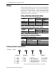
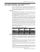
Installing Bulletin 500LC Lighting Contactors Ratings Bulletin 500LC Lighting Contactors are rated for 20 amps lighting loads and 30 amps general purpose. They are UL508 Listed, CSA Certified, and are available in 2–...12–pole single throw double break and 2–...6–pole normally open and normally closed configurations. Control voltages are from 120...480V AC. See Tables A, B, and C for contact ratings. Table A – Maximum AC Voltage and Amp.
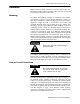
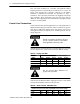
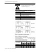
Installing Bulletin 500LC Lighting Contactors 3 Installation Bulletin 500LC Lighting Contactors are tested and ready to use. Installation simply requires mounting, and connection of line and load circuits and control circuit wires. Mounting Six outline and mounting drawings are furnished in this manual. Use Drawing A (page 5 top) for 500LC supplied in a surface or flush Type 1 enclosure. Use Drawing B (page 5 bottom) for 500LC supplied in a Type 3R, 4/4X, or 12 enclosure.
Installing Bulletin 500LC Lighting Contactors Line and load terminals are reversible. The Bulletin 500LC Lighting Contactor is UL Listed for use with 60 or 75˚ C wire. All power wires should enter enclosure adjacent to the 500LC terminals. Combination knockouts are provided on Type 1 enclosures. Line and load connections are supplied with clamp type terminals. These terminals accept the wire sizes #18–10 AWG Cu. Insert appropriate line and load wires and tighten clamp screws to 18 inch–pounds.
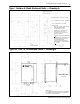
Installing Bulletin 500LC Lighting Contactors 5 Type 1 Surface & Flush Enclosed Units — Drawing A OPTIONAL FLUSH COVER 1.00 TYP ALL AROUND MOUNTED LIGHTING CONTACTOR LOCATION 1/2 & 3/4 KNOCKOUTS 2 PLACES ALL 4 SIDES 3/4 & 1.00 KNOCKOUTS ALL 4 SIDES SPECIFICATIONS: 1. NEMA TYPE 1 SCREW COVER, SURFACE MOUNTED CONSTRUCTED IN ACCORDANCE WITH UL–508. 2. MATERIAL: #16 (.060) GAUGE STEEL. 3. FINISH: ANSI #61 LIGHT GRAY. 4. NET WEIGHT 7 LBS, 3.2 KG WITHOUT LIGHTING CONTACTOR. 5.
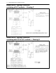
Installing Bulletin 500LC Lighting Contactors Bulletin 500LC Lighting Contactors containing all N/O contacts — Drawing C CONTACTS 1–6 AND 7–12 WILL BE OPENED BY APPLYING VOLTAGE TO “L” AND “O”. CONTACTS 1–6 AND 7–12 WILL BE CLOSED BY APPLYING VOLTAGE TO “L” AND “C”.
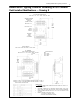
Installing Bulletin 500LC Lighting Contactors 7 Bulletin 500LC Lighting Contactor containing all N/O contacts Field Installed Modifications — Drawing E 2 – 6 POLE WITH OPTIONAL MODIFICATIONS MOD. 500LC–141C, –142C, –47CM*, –48CM*, OR –49SS* REFERENCE NUMBER DENOTES POLE LOCATION (REFER TO CHART) MOD. 500LC–141C 7.30 185.4 MAX. MOD. 500LC–142C 6.50 165.1 BLACK ORANGE 2–6 POLES BROWN MOUNTING HOLES ACCEPT #10 SCREWS 3.75 95.3 4.30 109.2 MAX. CONTROL MODULE MOD.
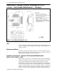
Installing Bulletin 500LC Lighting Contactors Bulletin 500LC Lighting Contactor containing N/O & N/C contacts Field Installed Modifications — Drawing F Kits Kits are available for modification of Bulletin 500LC Lighting Contactors to allow changes in pole configuration, voltage, control modules, and auxiliary contacts. Replacement Parts The main contact blocks and the operator coil are available in kit form. When ordering parts, provide the Serial No. and Catalog No.
Installing Bulletin 500LC Lighting Contactors 9 Solid–state Control Modules – Field Installed Modifications 500LC–47CM*, 500LC–48CM*, 500LC–49SS* These control modules are to be connected and mounted on the bottom or right side of the Bulletin 500LC Lighting Contactor depending on the number of 500LC poles or N/O and N/C contact configuration. A control module can be field installed by ordering the appropriate module kit. Refer to wiring diagrams on page 13 or 14. Operation Mod.
Installing Bulletin 500LC Lighting Contactors For DC modules be sure to connect terminal 4 to negative (–). Table G – Connections to Solid–State Control Modules Module Terminal Connected To 1 not used 2 control station for Mod. 500LC–48CM*, 500LC–49SS* 4 control station for Mod.
Installing Bulletin 500LC Lighting Contactors 11 Bulletin 500LC Lighting Contactors containing all N/O contacts LC BULLETIN 500LC LIGHTING CONTACTOR (WHEN USED WITH UL67 LISTED PANELBOARD) IS SUITABLE FOR USE IN A CIRCUIT CAPABLE OF DELIVERING NOT MORE THAN THE RMS SYMMETRICAL CURRENT AT THE MAXIMUM VOLTAGE SHOWN BELOW, WHEN PROTECTED BY A 30 AMP CIRCUIT BREAKER HAVING AN INTERRUPTING RATING NOT LESS THEN VALUES SHOWN.
Installing Bulletin 500LC Lighting Contactors Bulletin 500LC Lighting Contactors containing both N/O & N/C contacts LC BULLETIN 500LC LIGHTING CONTACTOR (WHEN USED WITH UL67 LISTED PANELBOARD) Publication 500LC–IN001A–EN–P May 2005
Installing Bulletin 500LC Lighting Contactors 13 Bulletin 500LC Lighting Contactors containing all N/O contacts with Field Installed Modifications REFERENCE NUMBER DENOTES POLE LOCATION (REFER TO CHART) OPTIONAL AUXILIARY CONTACTS OPTIONAL AUXILIARY CONTACTS LC LC MOD. 500LC–47CM*, 500LC–48CM*, or 500LC–49SS* MOD. 500LC–47CM*, 500LC–48CM*, or 500LC–49SS* AUXILIARY CONTACT RATING 2 WIRE CONTROL MOD. 500LC–47CM* 10A, 1/3 HP 277 VAC 0.5A, 125 VDC 0.
Installing Bulletin 500LC Lighting Contactors Bulletin 500LC Lighting Contactors containing both N/O & N/C contacts with Field Installed Modifications AUXILIARY CONTACT RATING 10A, 1/3 HP 277 VAC 0.5A, 125 VDC 0.25A, 250 VDC LC 500LC–141C (1PDT) 500LC–142C (2PDT) MOD. 500LC–47CM*, 500LC–48CM*, or 500LC–49SS* 2 WIRE CONTROL MOD.
Installing Bulletin 500LC Lighting Contactors 15 CAUTION The Bulletin 500LC Lighting Contactor is energized. Proceed with care! Trouble–Shooting Problem Check Control Voltage Check Control Station, Wiring, Supply 500LC does not close when control station is closed. 500LC does not open when control station is closed. Measure control voltage between 500LC terminals L and C. Measure control voltage between 500LC terminals L and O. 500LC tries to close or open, but cannot.
Installing Bulletin 500LC Lighting Contactors www.rockwellautomation.com Corporate Headquarters Rockwell Automation, 777 East Wisconsin Avenue, Suite 1400, Milwaukee, WI 53202–5302 USA, Tel: (1) 414.212.5200, Fax: (1) 414.212.5201 Headquarters for Allen–Bradley Products, Rockwell Software Products and Global Manufacturing Solutions Americas: Rockwell Automation, 1201 South Second Street, Milwaukee, WI 53204–2496 USA, Tel: (1) 414.382.2000, Fax: (1) 414.382.