
Manual
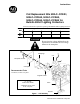

Installing Coil Replacement Kits 500LC–CCKA1, 2, 3, 4, 5 in Bulletin 500LC Lighting Contactors
3
Publication 500LC–IN002A–EN–P May 2005
Reassembly
Be sure that the control voltage stamped on the replacement coil is the same as
the coil voltage on the nameplate.
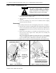
1. Install the new coil in the magnetic frame. Position the frame with the seam
facing the base. Position the new coil with the small hole outward and slide i t
into the right side of the magnetic frame.
2. Install the coil assembly onto the base (cam/core fits into the coil). Be sure the
magnetic frame is flat against the base. On 2–...6–pole contactors reinstall
and hold the lower actuator while reinstalling the leafspring and nameplate
onto the magnetic frame. The leaf spring is not used on 8–...12–pole
contactors. Then reinstall the two screws and tighten them to 10 in–lb. See
Figure 1.
3. Connect the coil. Connect the coil lead with the lug to the push–on terminal on
the miniatu re sw ic h . Connec t the bare c oil l ead to clos es t top sc r ew term in al
(und er plate). See Figur e 2.
4. Insert the plasti c screw from the kit into the center of the coil and carefully
turnitclockwiseuntilthethreadsengagethecam/core.SeeFigure3.
5. Manually operate the lighting contactor. Use t he plastic screw to close and
open the contactor by pushing it inward and pulling it outward. The acti on
should be smooth, wi thout any binding. If not, recheck a li gnment of coi l
assembly. See Figure 3.
Remove the p last ic oper at in g scr ew !
6. Remove the plastic operating screw from the lighting contactor.
7. Reinstall the lighting contactor into the enclosure and tighten the mounting
screws.
8. Reconnect all wires previously removed. Tighten control connections to 10
in–lb. Tighten the line and load connections to 18 in–lb.
9. Closecircuit breakers and check electrical operation of the lightingcontactor.