
Manual

Installing Control Modules Modification 500LC–47CM*, 48CM*, 49SS* to Bulletin 500LC Lighting Contactors
3
Publication 500LC–IN005A–EN–P May 2005
Connections
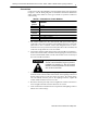
Connections to the Control Modules are shown in Table B. Also refer to the labels
in Figure 3 and the Wiring Diagrams in Installation Instructions Publication
500LC–IN001A–EN–P. Barrier screw type terminals accept #22–12 AWG Cu
control wiring.
Table B – Connections to Control Modules
Control
M
o
d
u
l
e
C
o
n
n
e
c
t
T
o
M
o
d
u
l
e
Te r m i n a l
C
onnec
t
T
o
1 not used
2 control station for 500LC–48CM*, 500LC–49SS*
3 control station for 500LC–47CM*, 500LC–48CM*, 500LC–49SS*
4see
CAUTION
control module control voltage
5 Lighting Contactor control voltage
O O on Lighting Contactor
C C on Lighting Contact or
1. The control modules have two colored leads with quick connect lugs for
connecting to the O and C terminal on the Lighting Contactor. Connect the
yellow wire to the O termin al; connect the orange/black wire to the C
terminal. For reverse operation connect the yellow wire to the C terminal, and
connect the orange/black wire to the O terminal.
2. Connect the external control wiri ng for the control module to terminals 2, 3,
and 4 on the control module as shown o n the wiring diagram. Te rminal 2 is not
used on Control Module 500LC–47CM* and terminal 1 is not used on any of
the control modules listed here.
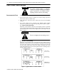
F or DC control modules be sure to connect
ter min al 4 to n eg at ive (–) . For AC cont r o l
modules connect terminal 4 to the neutral
wire of the control line.
3. Conne ct the control wi ring for the Lighting Contactor (coil voltage) to
terminal 5 on the control module a nd terminal L on the Lighting Contactor. If
the line voltage (service) is the same as the coil voltage, the control voltage
can come directly from the poles of the Lighting Contactor. Tighten all
control module terminal screws to 12 in–lbs.
4. Reconnect all wires previously removed. Tighten the control connectio ns to
10 in–lb. Tighten the line and load connections to 18 in–lb.
5. Close circuit breakers and check electrical operation of the lighting contactor
with the new control voltage.